One of my goals when I came to Recurse Center was to “get better at hardware,” which was admittedly somewhat of a vague goal. Without an obvious problem that I needed to solve with hardware, it was hard to decide what to build. After soaking up some of the playful energy here at RC, a brief exploration with a simple Simon Says game, I landed on Beep It!, a clunky remake of the classic 90s Bop It! game.
This seemed like a good way to expand my hardware skills in a few ways:
- I wanted to design a container for the box so that the game could be safely protected from playing hands (and “easily” transported).
- I wanted to be able to move past the breadboard prototyping phase. Because interactions with Beep It! can get a bit rough (😅), I had to figure out how to solder the pieces together in a more durable and permanent manner.
- I wanted the game to be portable, and thus, battery powered.
- I wanted to get more familiar with more types of sensors and protocols, of which Beep It has many!
Here’s a quick write up of the implementation and what I learned.
Materials
The gameplay for Beep It! requires the user to perform the requested action by the game, which required a number of sensors. I decided to build the following interactions for the game:
- Raspberry Pi Pico: The Pico is a really good option for the game because it’s very low power so it can easily be powered by a battery. It also has three analog pins so I didn’t need to deal with an analog-to-digital converter. The I2C pins were also pretty easy to work with.
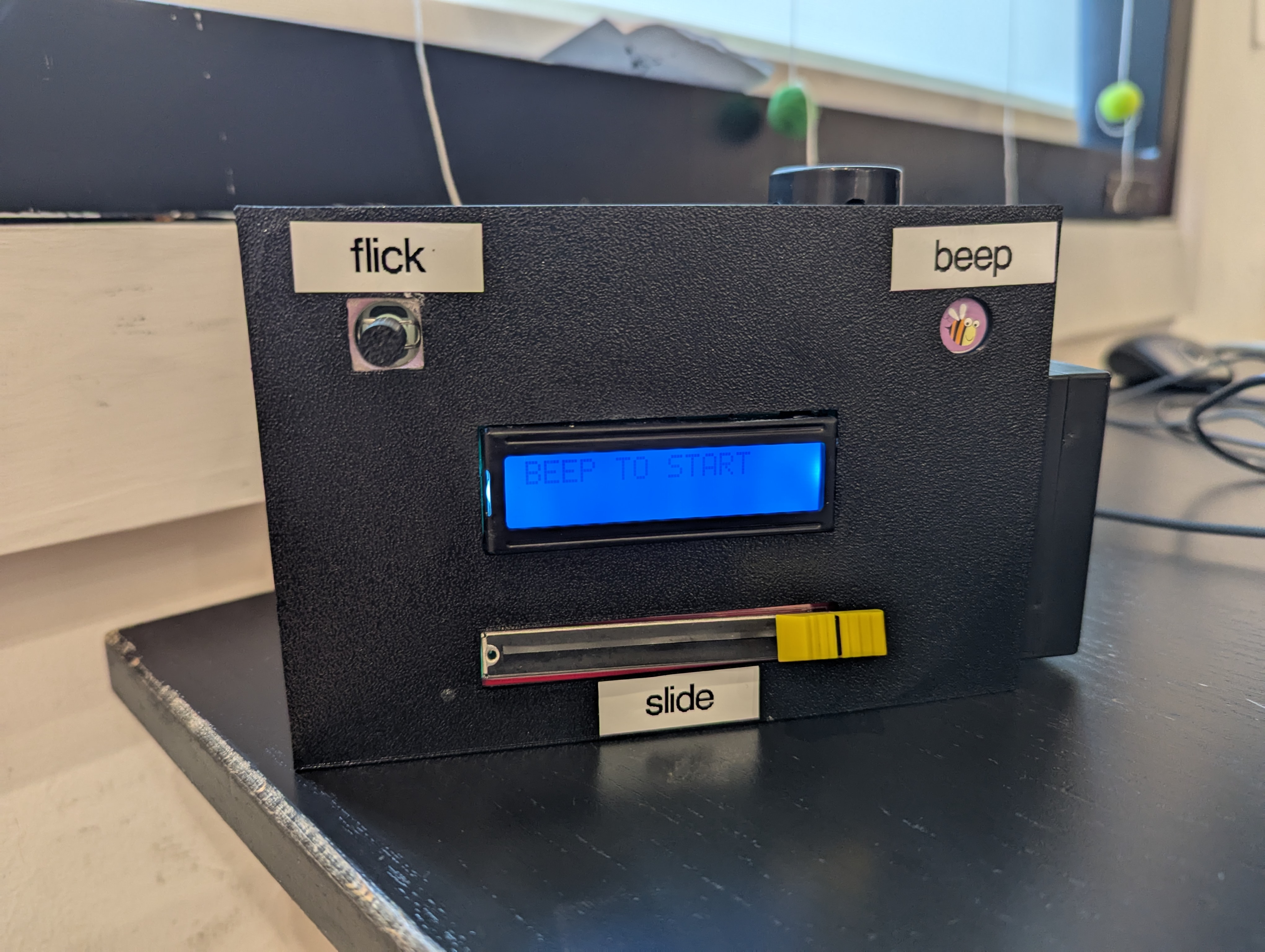
- Beep It! This is powered by a TTP223B1 Touch Sensor. This sensor worked really well as it registers touch on both sides of the sensor, and can also register touch through other materials. I decided to protect the sensor with small sticker and found a cute little bee sticker, so that’s how the Beep It! name was born.
- Shake It! The shake action is powered by an MPU6050 6-degree-of-freedom sensor. I think shaking is the scariest part of the game because all the hardware just kinda clunks around in the box. But, I don’t think it would be as fun without it.
- Slide It! This is powered by a slide potentiometer! This is connected to one of the analog pins.
- Flick It! powered by a KY023 Joystick. This sensor connects to the other two analog pins (for the x and y movement). The joystick can also register a click event but that wasn’t relevant for Beep It!, so I left that pin alone.
There are a couple types of output / feedback for the player of the game:
- 16x2 LCD Display: The display is the primary mode of instruction. This device prints out instructions (such as which move to make), feedback on whether the player took the correct move, and a final score.
- Piezo Buzzer: The buzzer adds another layer of excitement to the game. It
plays a short song on game start up, has a custom sound for each movement, and
buzzes if the player gets the move wrong. The piezo ended up being a really good
simple solution for folding audio into the game. My original plan was to figure
out how to hook up a speaker that would play
.wavfiles but the wiring and components required were adding a layer of complexity I wasn’t ready to deal with.
Soe of the sensors were available in a Sunfounder Hardware Kit I had purchased, which also has a very nice set of tutorials. The other sensors I didn’t have access to were easily purchased on Amazon!
Designing the circuits
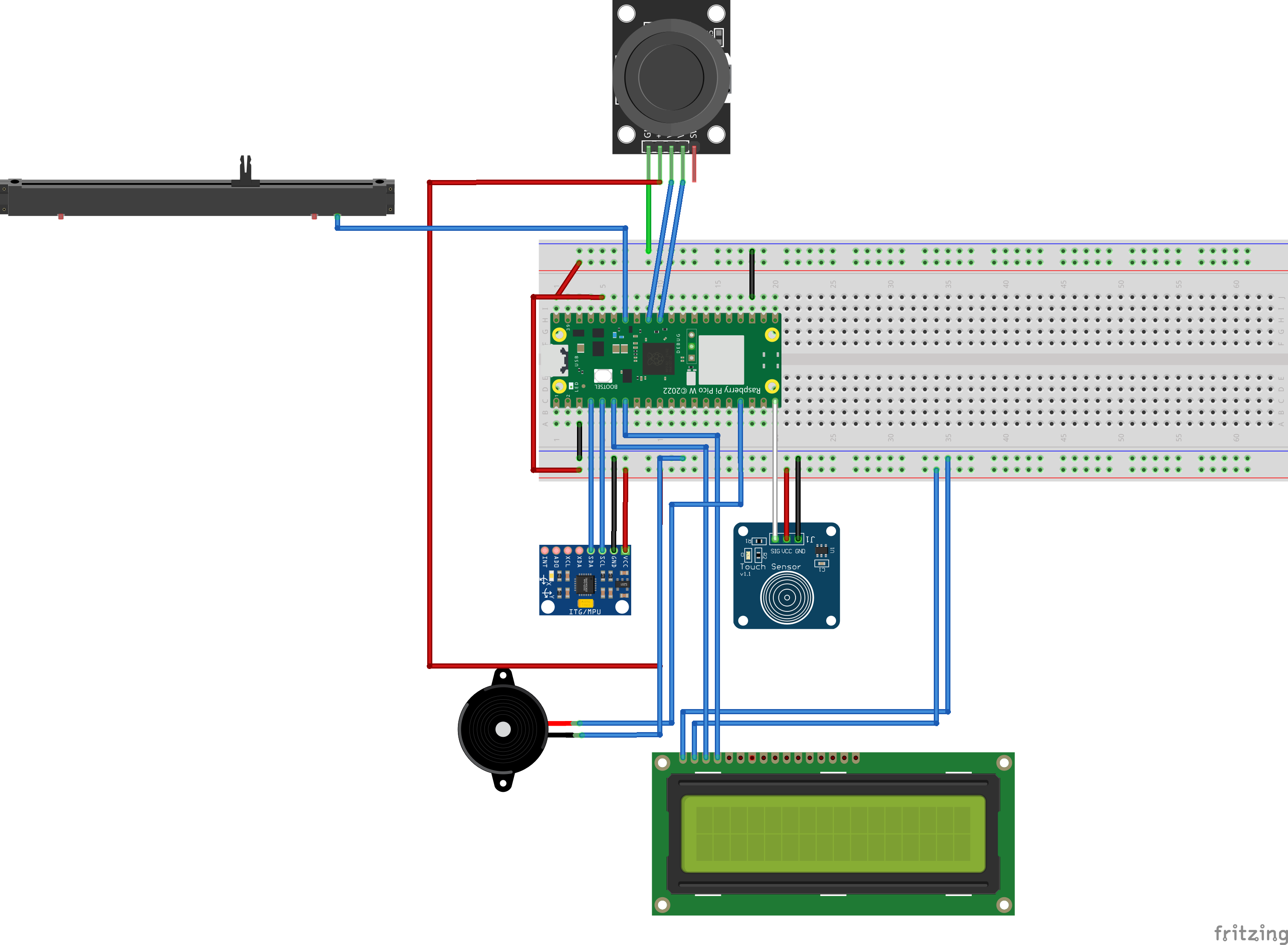
Because the game has so many sensors, I wanted to be very intentional about what pins I was using. I also wanted to document the schematic so it would be easier to translate it from the breadboard prototype to a more “permanently” wired game.
Enter Fritzing! I found this software to be super helpful for designing and translating the schematic. I was able to find fritzing files for most of the sensors I had purchased, with the exception of the slide potentiometer.
Here’s the schematic I ended up with:
Wiring the circuits
The final translated wiring looks a bit different, as the wiring for the power and ground was getting a bit unwieldy, so some of the power and ground wires connect directly to the Pico, while some others are connected in a sort of “power bank” type of solder mess. :)
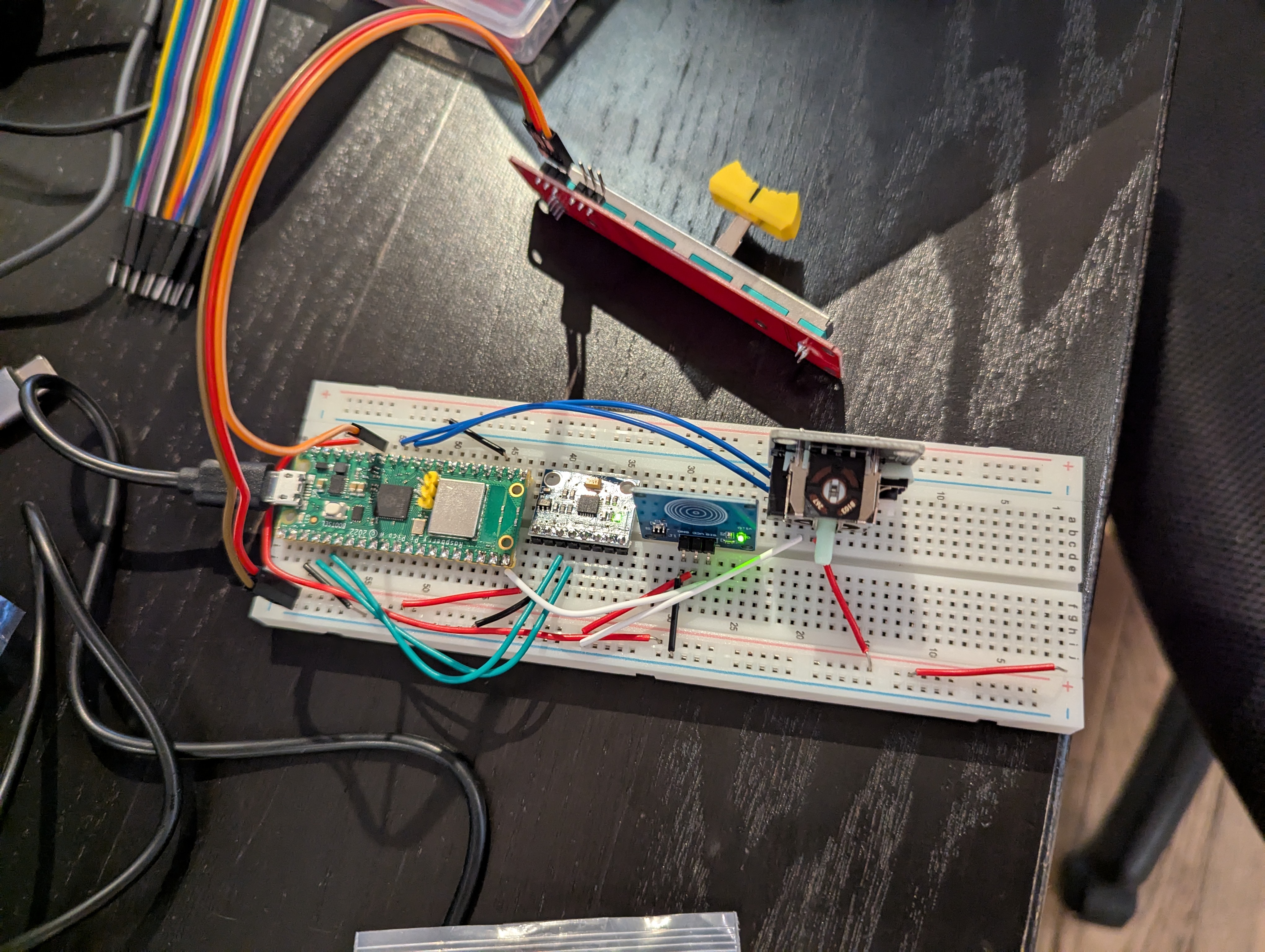
Here’s what (almost) everything looked like when it was wired via the breadboard. It was quite hard to test with everything hooked up this way!
And here’s what everything looked like once the wiring had been translated to a PCB board.
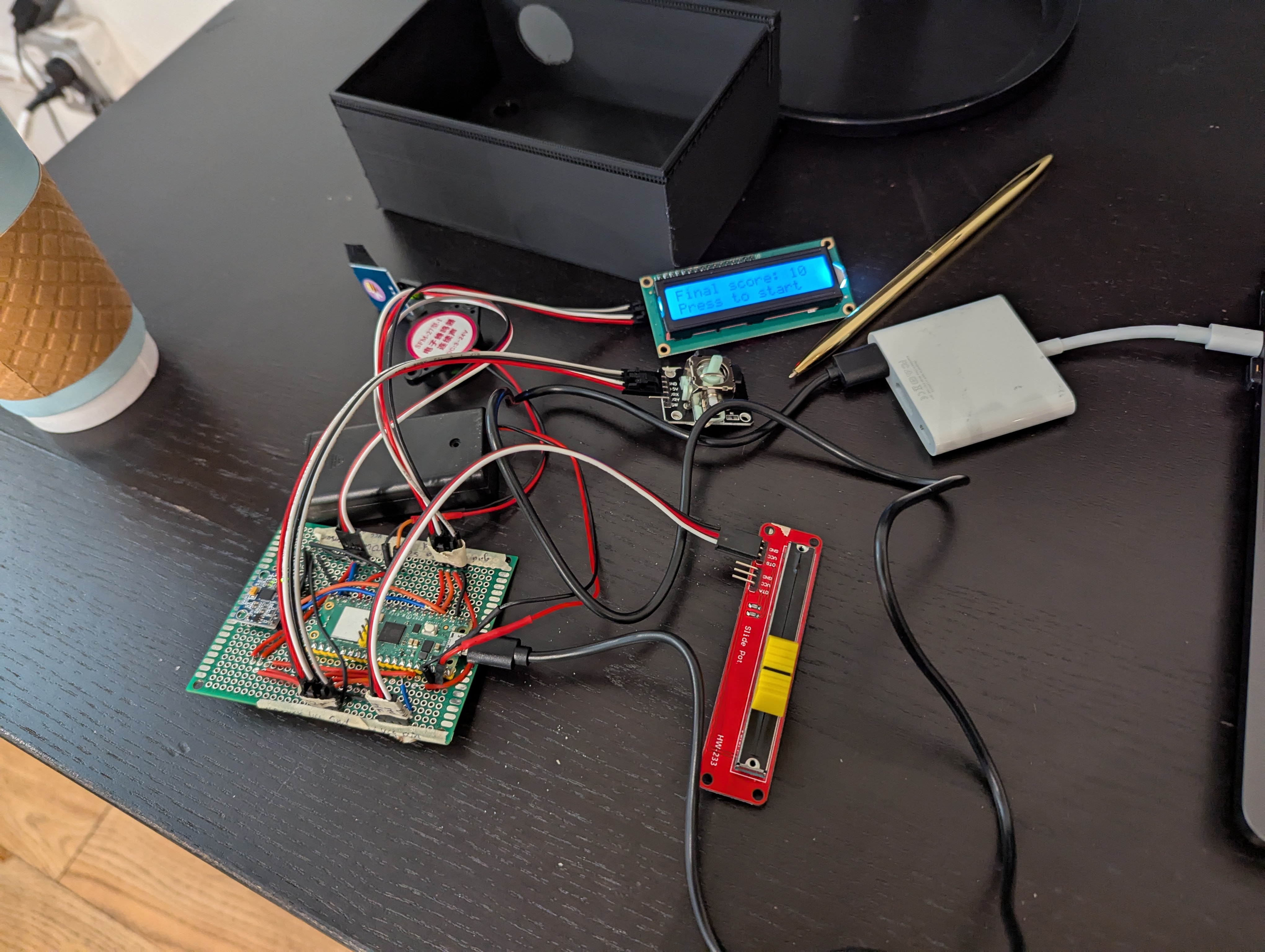
It was quite the mess of wires and solder. This was my first time soldering “for real” and I found it quite tricky. Getting the solder to flow “just right” was very difficult and the end result is very messy. I did have to debug the circuits a bit as some of the connections were a bit shoddy on my first attempt. I think it also probably took me 5 times longer to complete all the soldering than it would have for someone more experienced.
What I do like about the “finished” result is that only the battery and the piezo are hard wired to the device. All other sensors can be easily disconnected so I can get them nestled in the box before connecting the board to them.
Building the game logic
The software for the game felt like the most straightforward part of this project.
Writing software for the Pico ended up being much more delightful than I expected! A few tools that helped me get this part up and running quickly were:
- MicroPico VS Code Extension which allows for super easy connection to the hardware device via serial. This opens a REPL on the device and allows for super easy debugging of the code. I am really glad I found this; the tutorial I had been following was using Thonny which was not sparking joy for me. It was nice to be able to use the tools I was already comfortable with!
- MicroPython in general was so easy to work with! The one tricky thing I ran into here was figuring out how to import libraries that are specific to the Pico. I ended up just copy-pasting some of the necessary libraries (such as i2c lcd) into my project for use which is apparently a legit thing to do.
The game logic itself is relatively straightforward. The biggest problem in the logic was having to correctly handle debounces and fine tuning the sensitivity for each sensor. One way I solved for debounces was by adding more of a delay in between the instructions. At first this felt like cheating, but the delay I currently have in place seems to feel pretty good during game play so I’ll probably not mess with it too much.
To deal with the sensor sensitivity, I did a lot of debugging by connecting the device via the USB port and printing out sensor readings. This helped me figure out what the right thresholds were for each sensor. One of the more interesting findings was that the joystick seemed to work well until I attached everything to the box. It seems that I got some glue on the joystick and it started reading somewhat inconsistent values in the default position. This was easy enough to address by only responding to very high or very low values.
Designing the game box
Beep It! isn’t Beep It! without a box. I wanted to design a box that would give the player easy (enough) access to the sensors without having to move their hands too much, would protect the game, and wouldn’t be too big or unwieldy.
Luckily, Recurse Center has a 3d printer that I had done one test print on before, so I decided it was time to figure out how to design my own 3d printed element.
After taking a look at AutoCAD, FreeCAD, and Blender, I felt totally overwhelmed. It felt like it’d be a really big time investment to learn how to use any of those tools and I wasn’t sure it would work. Then I stumbled upon Tinkercad which was the perfect fit for me. It had great tutorials and makes building simple shapes very easy. Shapes and holes are very easy to create and position, and to specify exact measurements.
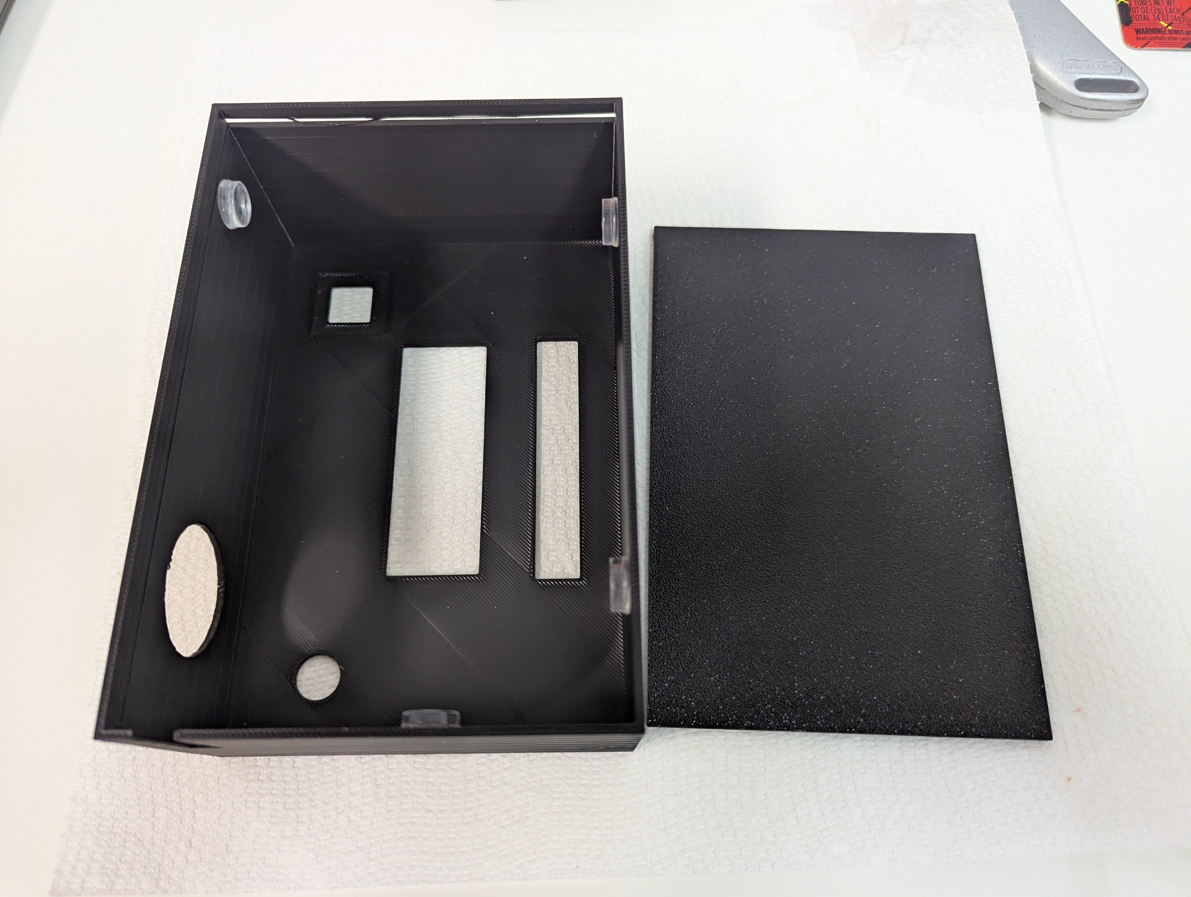
I attempted a couple different designs before settling on the final box design. This design has all sensors on the front / top of the box so the player could place the box on a table or desk to play if they felt it was a bit too big to handle.
The box has holes to expose each of the sensors, a sliding bottom cover, and a slot for the battery and debugging cable.
Printing the box on the printer took quite some time, as the printer at RC has been a bit finicky and the print requires some babysitting. But after a few hours, the box was finally done!
Assembling it all together
Once the code was (mostly) working and all the pieces built, it was time to assemble it. Unfortunately, some of the sensors weren’t designed in a way that they could be (easily) mounted, so I had to get a bit creative.
The touch sensor and the joystick were somewhat easily glued to the box, while the LCD display and the slider had to be (strategically) taped to the inside of the box. This isn’t particularly durable and the slider has had to be re-taped a few times. I’d like to come up with something more permanent here but I might have to look for a different sensor.
Since the sensors are detachable from the main PCB board via header pins and pluggable cables, it’s easy to pull the PCB board out if, for example, some of the soldering needs to be fixed. 😉
Once the sensors are mounted into the device, it’s simple enough to connect everything, velcro the battery pack to the outside of the box, and slide the lid shut.
And voilà, we have a working game!
Wrapping up
While this wasn’t necessarily a capstone project for my time at RC, it was definitely my most involved project, which required a decent time investment and lots of learning at the edge of my abilities. I have to say, I’m pretty impressed with how the end result turned out. When I first decided “sure, I’ll build bop it,” I had no idea how I’d even go about it. But, just like a software project, breaking the problem down into iterative steps helped me stay focused and take it one day at a time.
Of course, unlike software projects, a bit more advance planning was necessary. I wasn’t quite sure how to approach building the sound and kind of just made some guesses about what would work. In retrospect, I think I should have done a bit more research about which exact sensors I needed and made sure that the Pico would be able to handle all of them. I would have also spent a bit more time confirming measurements of the designed box before attempting the first 3d print.
I’m excited to take these learnings with me to my next hardware project, whatever that may be!
Some references: