I'm finally taking a crack at writing a sequencer for the Yocto drum machine. Last time I wrote about making progress but lacking MIDI synchronization.
Recap
Drum pattern editing was working but my sequencer firmware would only run off the internal clock (generated using the "output compare" function of the machine's ATmega1284P MCU). For the way I make music, it would be practical if the Yocto could also follow an external MIDI clock.
The original firmware can do this of course, but I'm writing my own so incoming MIDI clock won't do anything until I write code that listens to it!
Clock sync strategies
Before I got started I could think of two strategies to implement synchronization to an external clock. One is to synchronize the internal clock to the external clock, and the other is to replace the internal clock with the external clock.
Replacing the clock signal is not an option if your internal clock runs at a different frequency from the external clock, but in my case the frequencies are the same: both MIDI clock and my 808-inspired sequencer run at 24 pulses per quarter note (PPQN).
I decided that replacing the clock would be simpler than implementing synchronization. With clock replacement I don't have to worry about tempo changes in the external clock.
How does it work
You can see the current code here.
I introduced two new state variables: midiactive and midiclock. The first one determines whether we follow the internal clock or the external MIDI clock. The second one counts how many unprocessed MIDI clock ticks we have received.
Because clock-related MIDI messages are just single bytes we don't even need a MIDI parser.
while (uart_read(&b)) {
    if (b == 0xf8) {   /* MIDI clock */
        midiclock++;
    } else if (b == 0xfa) { /* start */
        clock = -1;
        running = 1;
    } else if (b == 0xfb) { /* continue */
        running = 1;
    } else if (b == 0xfc) { /* stop */
        running = 0;
    }
}
The if statement that checks whether the internal clock has ticked used to look like this:
if (TIFR1 & 1 << OCF1A)) {
    TIFR1 |= 1 << OCF1A;
    /* ... generate output for 1 clock tick ... */
}
Now it does this:
if ((!midiactive && TIFR1 & 1 << OCF1A) ||
    (midiactive && midiclock)) {
    TIFR1 |= 1 << OCF1A;
    midiclock -= midiclock > 0;
Once I got it all working the change turned out quite small.
Getting stuck
I got stuck a couple of times.
Automatically disabling the internal clock
At first I was over-optimistic and I tried to make too many changes at the same time. I wanted to have automatic detection of the external clock. If we receive MIDI clock pulses, switch to external clocking. If we receive none for a while go back to the internal clock. It seems simple enough but it wasn't working and the number of lines changed made it too hard to find out what was wrong.
Prefer small steps!
On my second try I used the mode selector dial of the Yocto to set the value of the midiactive variable. It's up to the user to decide which clock to follow.
"Simplifying" the UART polling
MIDI is built on top of a protocol called "universal asynchronous receiver-transmitter" (UART). While working on the MIDI sync I "simplified" the code that reads from the MCU UART peripheral to the point where it stopped working. It cost me a lot of time to find the problem.
This is the code that worked and that I should have kept:
/* GOOD */
uint8_t uart_read(uint8_t *data) {
    if (!(UCSR1A & 1 << RXC1))
        return 0;
    *data = UDR1;
    return 1;
}
If there is a new UART message, signified by the RXC1 bit being set in UCSR1A, this function stores the message at the data pointer and returns 1. Otherwise it returns 0.
This is the broken code I "simplified" to:
/* BAD !!! */
uint8_t uart_read(uint8_t *data) {
    uint8_t ret = (UCSR1A & 1 << RXC1) > 0;
    *data = UDR1;
    return ret;
}
Naively, the only difference between the two is whether *data get overwritten, and the callers of uart_read don't look at *data when the return value is 0. So this second version should work the same.
But the UDR1 "variable" is special. It is really a macro and if you evaluate the macro, that line says:
*data = *(volatile uint8_t *)(0xce);This 0xce is a magic memory address and reading from it (yes, reading!) has side effects. The first version of the function does not read from 0xce unless RXC1 is set, but the second version always reads it.
I don't know why, but this doesn't work correctly. It could be a "time of check to time of use" race condition (TOCTTOU)
between checking the RXC1 flag and reading UDR1, or it could be that reading UDR1 before reception is complete messes up the internal state of the UART receiver.
Either way, if I drop in the second version of uart_read the bug comes back again: clock messages get lost.
This bug drove me nuts and I started to consider desparate theories. At one point I wondered if the MIDI clock messages were coming in too fast for my code to handle them and I switched to using an interrupt. This made the bug go away! However, this made no sense because MIDI is so slow we shouldn't need an interrupt.
Why using an interrupt makes no sense
Interrupts are a control flow mechanism that let the microcontroller react to certain events, like the arrival of a UART message, by literally interrupting whatever the microcontroller is doing the moment the event occurs. They are useful if you need to react to an event quickly in the middle of a slow task, or for things like waking up from sleep.
In my firmware projects I avoid using interrupts where I can because they can cause subtle concurrency bugs. (This may be an unusual preference.) In the case of receiving MIDI UART data on the ATmega1284P, I don't see a need to use an interrupt, because there should be enough time to poll instead.
MIDI operates at 31250 baud (bits per second). A MIDI UART message is 10 bits long (1 start bit, 8 data bits, 0 parity bits, 1 stop bit). Transmitting a message therefore takes (10/31250)s = 320µs.
The ATmega1284P UART receiver has an internal FIFO that holds 2 messages so in order to not lose messages, I must poll at least once every 2 * 320µs = 640µs.
The slowest instructions on the ATmega1284P (call, ret etc.) take 5 cycles. With the MCU running at 16MHz, the worst case instruction time is then (5/16000000)s = 0.3125µs.
The slowest thing I do in between polling the UART is polling the user interface buttons via SPI, 3 bytes at 8Mhz, which takes 3µs, and shaping the "common trigger" 808 sound generator pulse which uses a 4µs sleep. Unless I do something silly, I just don't see how I would use up that 640µs time budget.
So why did using a UART interrupt fix the bug? Because the interrupt only runs if the RXC1 bit is set. In the interrupt handler, the MCU prevents me from reading UDR1 at the wrong time.
Once I figured this out I got rid of the interrupt again.
It works (too well?)
To try out the MIDI synchronization I made a recording with a Roland TR-707 sending MIDI clock to the Yocto. I recorded the audio of the Yocto on the left and the TR-707 on the right.
I don't know if you can hear it but the Yocto is ahead of the TR-707. You can also see it if you look at the waveforms:
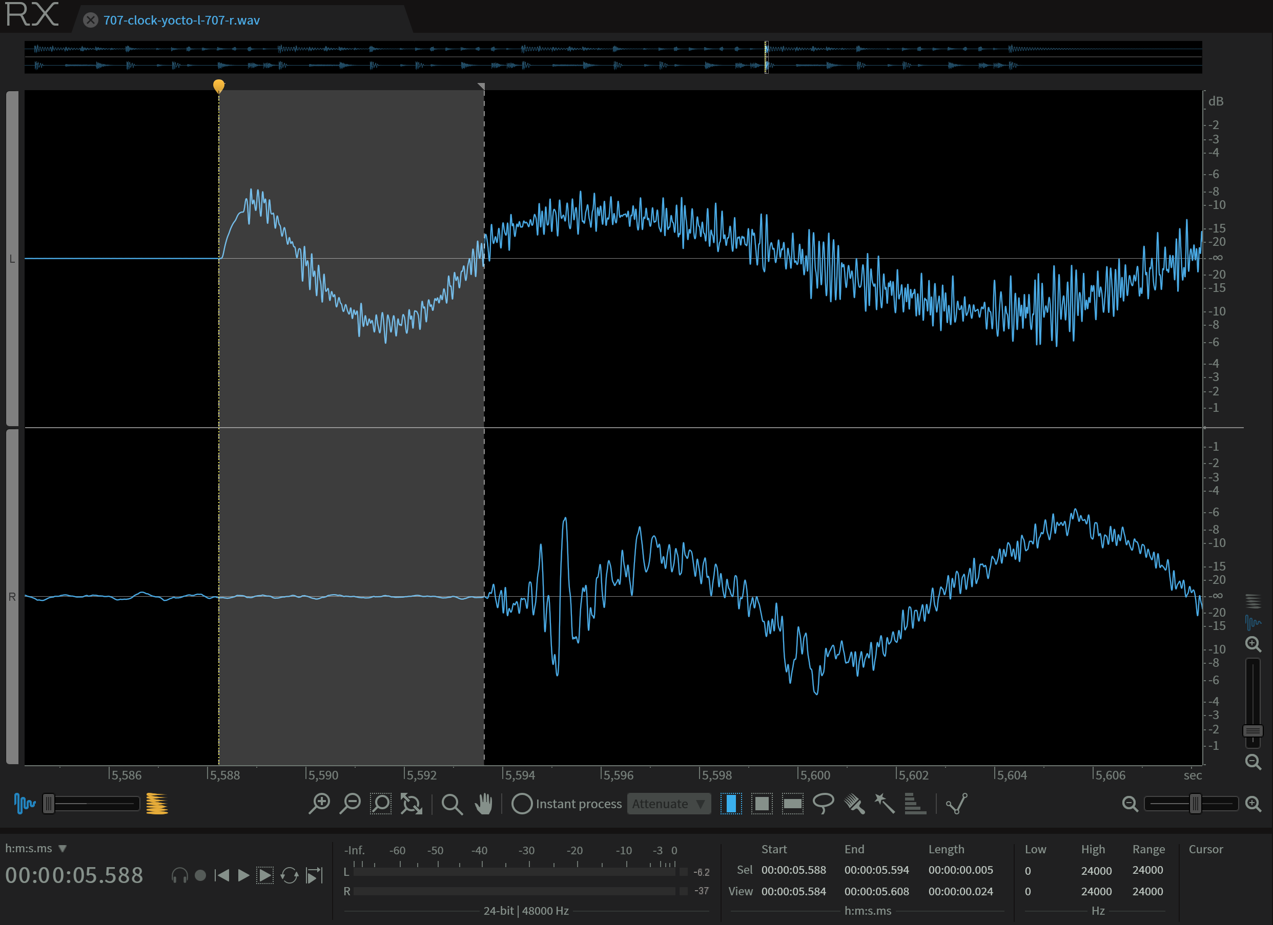
The time shift appears to be about 5ms (look for 'Sel' 'Length' in the lower right hand corner).
My guess is that this means the engineers who made the TR-707 assumed that the MIDI device receiving clock from the TR-707 would need 5ms to produce a sound in reaction to the clock, so they made the 707 send out the MIDI clocks early.
Even when I record into Reaper, most of the time the Yocto plays a fraction ahead of the DAW grid. It appears to be around 6 samples at 48kHz. I guess Reaper also makes assumptions about MIDI latency on the receiving end.
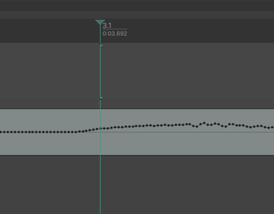
This goes to show how much MIDI latency can vary.
Conclusion
Naive MIDI sync, by replacing the internal clock, works. The 808 / Yocto sound generator circuits are very fast. Code golf is fun but sometimes I break things. Take small steps. If something doesn't make sense, keep digging.