Axiom: body hair is cringe. That's how I feel, at least. I decided to build a machine that lets me permanently remove it using electricity.
There are lots of ways to get rid of body hair temporarily. Shaving is probably the most common. There are other methods that last a little longer, like epilation or waxxing. These remove the entire hair, which takes more time to grow back than just cutting it at the surface.
If you're looking for something more permanent, laser hair removal is an option. This is when laser light is used to heat the follicles and kill them. Most people regard this as permanent, but it's really more of a permanent hair reduction, not overall removal.
There's actually only one type of hair removal that the FDA considers permanent, and that's hair electrolysis.
A brief primer on hair electrolysis
Now's as good a time as any to give you a little disclaimer. I am not a doctor. I have no qualifications on anything even remotely related to this project. I am just some cat on the internet who happens to own a soldering iron. Take everything I say with a huge grain of salt.
With that out of the way, let's talk about hair electrolysis. There are 3 main types:
Galvanic hair electrolysis is the simplest type. A needle is inserted into the follicle and a small current is applied for a few seconds. This causes lye (sodium hydroxide) to be generated through the chemical process of electrolysis. This lye permanently kills the follicle.
Thermolysis is technically not really electrolysis, but they get lumped together. A needle is still inserted, but this time, an RF current is applied. This causes very localized heating which kills the follicle. This process is much quicker - supposedly just a fraction of a second per follicle.
Blend electrolysis is where you use a combination of the two methods. A single needle is used, which applies both a DC current and RF current. This provides many of the advantages of both methods. My understanding is that this is the most common method in professional settings.
I chose to focus my efforts on building a galvanic machine. It's easier than RF magic, and I could generally find more information about the specifics. Even in textbooks, the specifications of the RF were hard to find. RF is generally a lot easier to mess up as well, which can cause burns or even scarring. Galvanic seems a little more idiot-proof. Of course, it's still possible to do some damage if you really try.
Some more depth on galvanic electrolysis
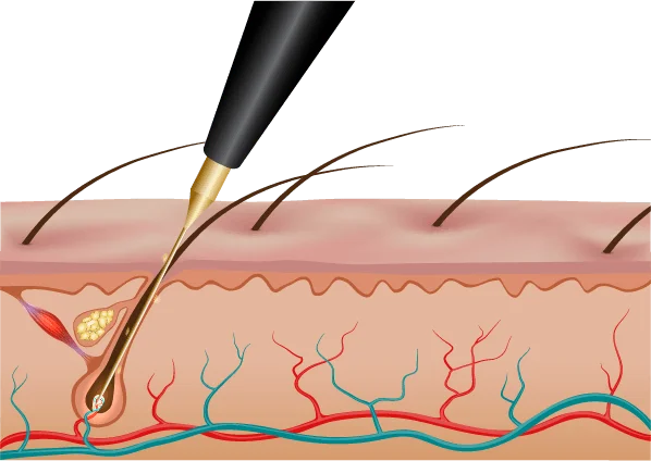
Since I'm going with galvanic electrolysis, I want to provide a little more information on it. Like I said before, we want to generate lye in the follicle. We do this by passing an electric current between two electrodes. One electrode is the needle which is inserted into the follicle. The other electrode goes on the outside of the body. Its location is not critical.
As it turns out, the amount of lye generated can be found by computing the integral of current over time. In the context of hair electrolysis, the amount of lye is specified in units of lye (LU), where 1 mA for 1 s produces 10 LU. Maximum current is generally limited by the user's pain tolerance, but lower current can be compensated for by running the machine for longer. It's actually pretty simple!
Here's a table of lye values, taken from a medical textbook titled "The Principles and Practice of Electrical Epilation" (3rd edition, 2001).
| Hair type | Amount of lye (LU) |
|---|---|
| Fine, unpigmented vellus hair | 10 - 15 |
| Fine, pigmented, soft hair | 10 - 20 |
| Medium/shallow terminal hair | 15 - 30 |
| Deep terminal hair | 30 - 45 |
| Very deep terminal hair | 45 - 60 |
With all of this in mind, I was ready to build my first prototype.
The prototype
I had most of what I needed lying around my apartment. One thing I didn't have was a needle for actually inserting into the follicle. Luckily my friend Olivia came in clutch; when I visited her in Portland she gave me 20 spare needles she had from her own hair electrolysis project.
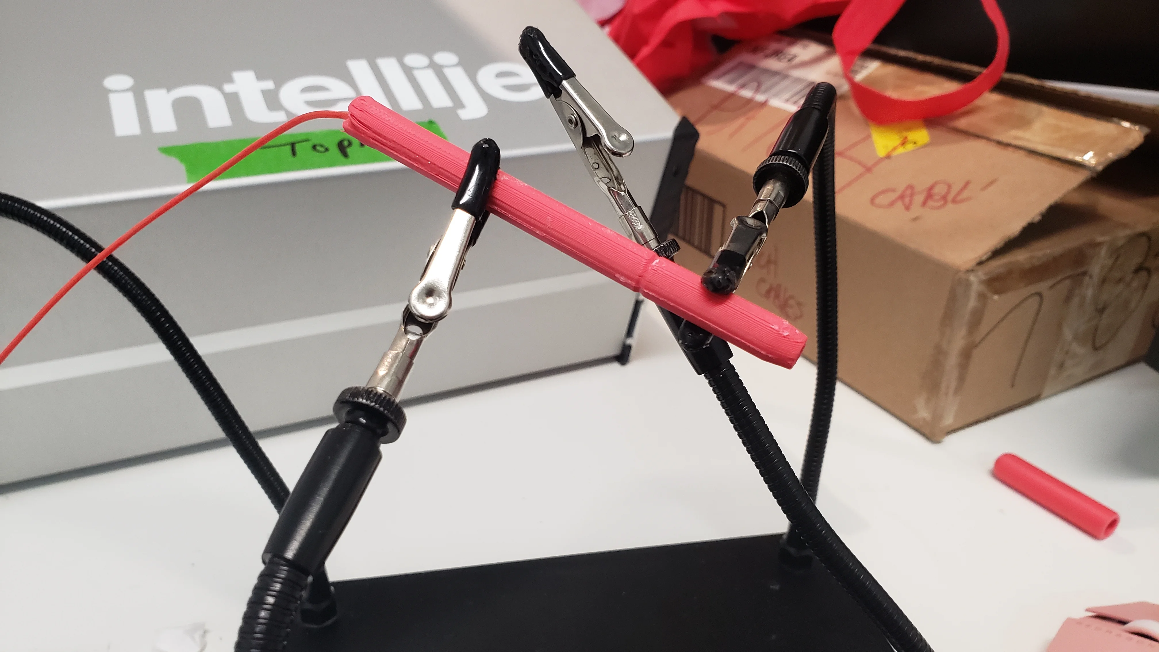
What I built for a first attempt was extremely crude. I connected the needle to a potentiometer, which was used for approximate current limiting, and then to a car battery. I also inserted a current meter into the circuit so I could monitor things. For the other electrode I used a pop can. Grabbing the can would complete the circuit and start the flow of electricity. One side effect of this is that I could loosely tune the current by how hard I squeezed the can. Squeezing harder would lower the resistance slightly and allow more current to flow.
This is what the result of my efforts looked like:
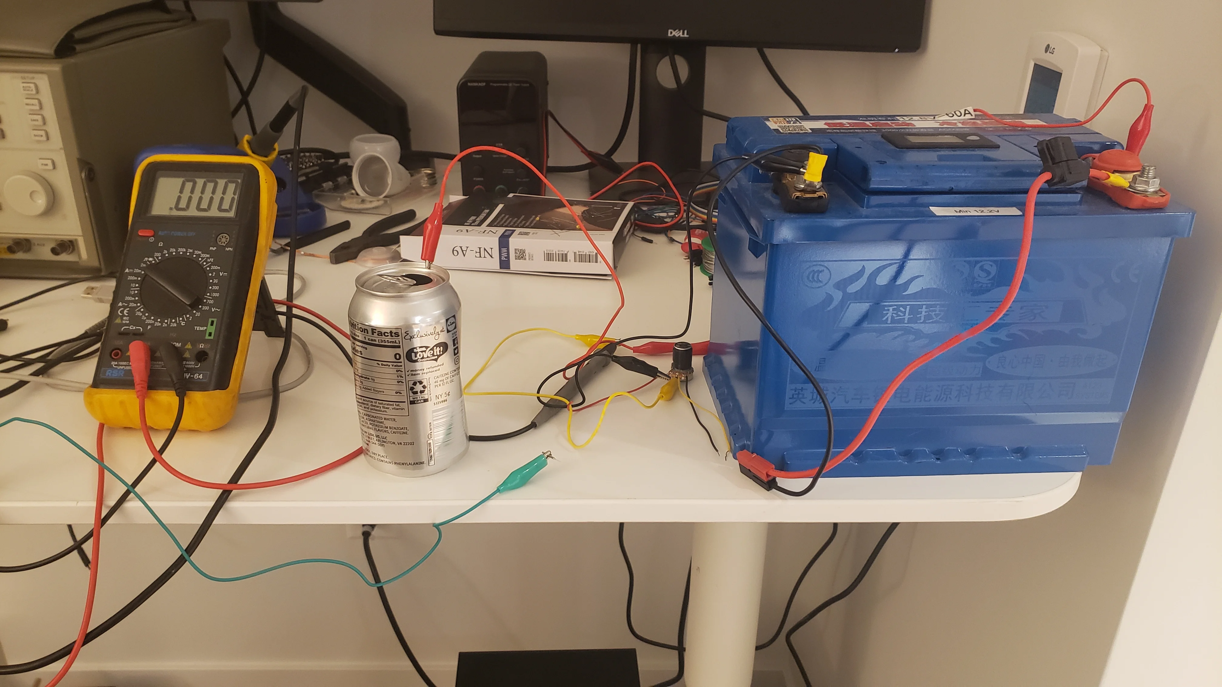
I'll admit that it doesn't look like the safest contraption in the world. I would watch the current meter and time it by counting seconds to work out roughly the amount of lye generated. Once I got to the target, I'd let go of the can. As janky as this was, I was able to successfully use it to remove some hair from my arm! This was a euphoric moment where I realized this project was going to work. The follicle that came out was enormous - it reminded me of epilation, except it came out with absolutely no resistance.
I'm pretty needle-phobic, but I really didn't mind inserting the needle. It's going into an existing hole, and it's so small that even when I miss the follicle it's still totally painless. In fact, many electrogists prefer calling it a probe rather than a needle, because it doesn't actually pierce anything. What made me squirm a bit was bottoming out the needle in the follicle - it's an uncomfortable sensation, but still not painful. The actual electricity did hurt a bit, but it wasn't as bad as I expected from what others told me. I'd subjectively say it's slightly more painful than laser hair removal.
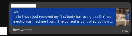
After my experimenting, I sent the above picture to a few friends with an explanation:
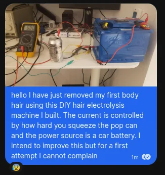
And got back a wide range of feedback:


Now that I had proven the proof of concept, it was time to turn this into something that was actually usable.
Improving the needle
One of the jankiest parts of this first iteration was actually manipulating the needle. I was just holding it with a pair of alligator clips, which made it difficult to control. Professional electrologists use what's called an electrolysis pen, which literally looks like a pen with an electrolysis needle sticking out.
Electrolysis equipment is generally crazily expensive, and electrolysis pens are no exception. As a result, I set out to build my own. The hardest part about this was figuring out how to grip the needle. I tried a bunch of things, but nothing really worked. Then, I heard from a friend of a friend that female DE-9 connector pins actually fit great. I was able to confirm this; it's not perfect as the needles are just a little wider than the male DE-9 pins, but the fit is very snug and secure.
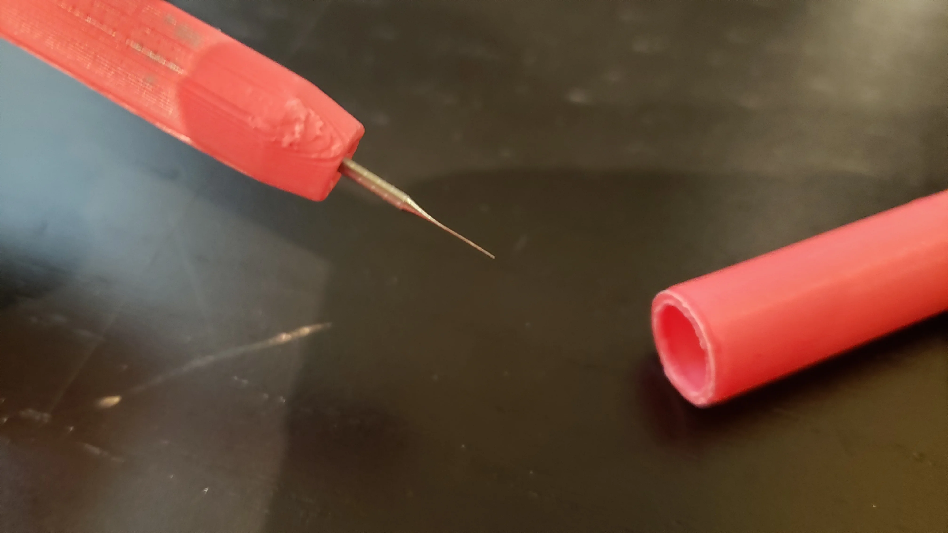
Now that I had the hard part figured out, I just had to go design and 3D print the actual pen. I threw something together in FreeCAD and printed it out in two parts.
I glued the pen parts together with the female pin in the middle. To be honest, I would have preferred something that hugged the pin snugly, but there were no good attachment points, and FDM printing is just too low fidelity. It turned out okay though, although getting the pin centered properly was finicky.
I also added a cap to protect the needle, primarily during transit. Embarrasingly, I printed everything red and used a red wire, but the needle is actually connected to the negative side of the current source. The polarity is important; getting this wrong will cause hydrochloric acid to be generated in the follicle instead of lye, which is much more prone to causing scarring!
Now let's build the actual machine.
Designing the real machine
People have a lot of hair follicles, so any manual steps are going to get monotonous and leave room for mistakes. As such, I want my machine to automate anything it can. Current needs to be set once and then accurately controlled. It should be switched on by a foot pedal, and switched off automatically when the target amount of lye is generated. It should also ramp the current up at start time and down at stop time to make it less painful. For practicality, the machine should be small and battery powered. Finally, it should be reasonably safe; the machine should be physically incapable of providing a dangerous amount of current.
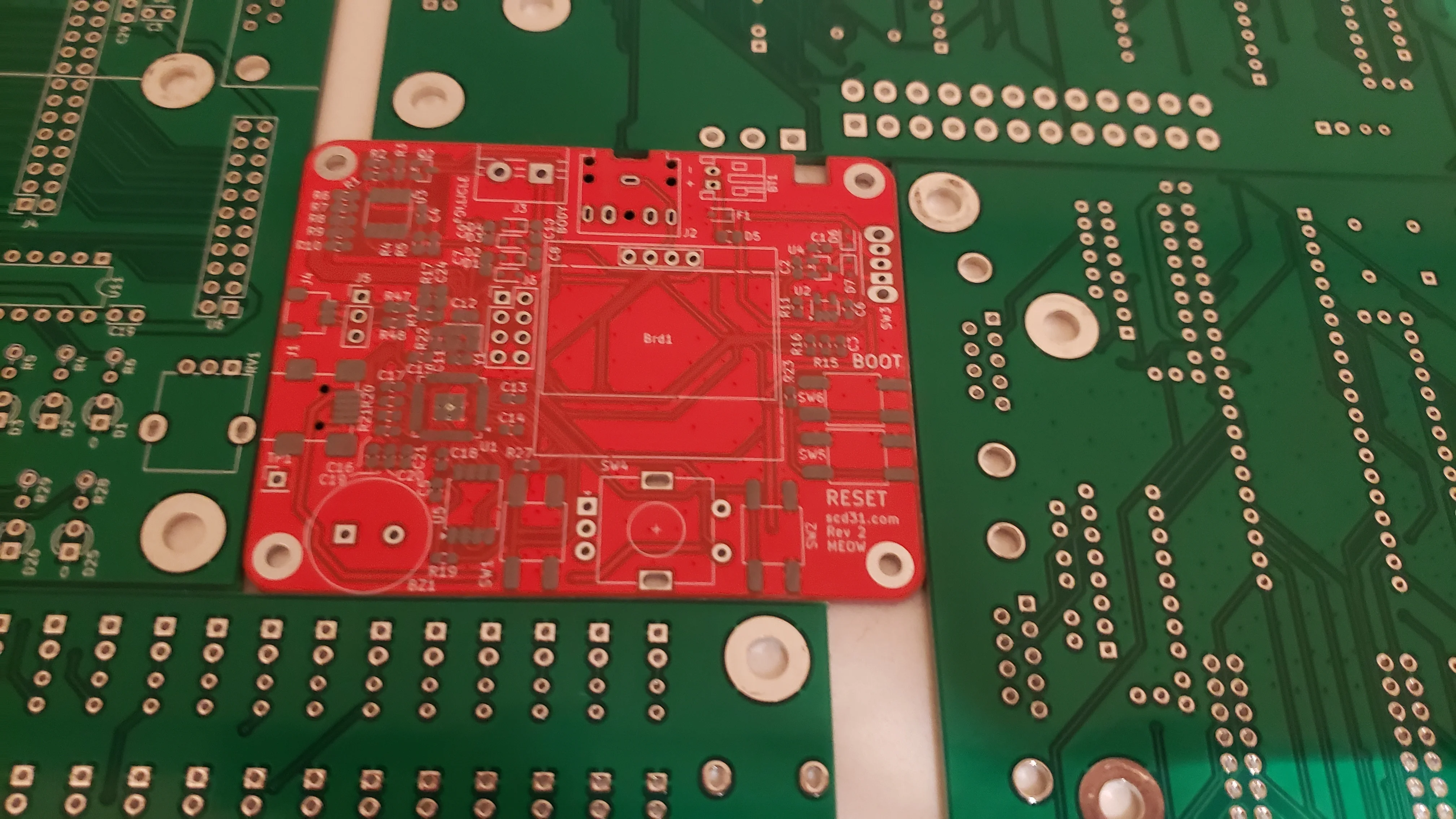
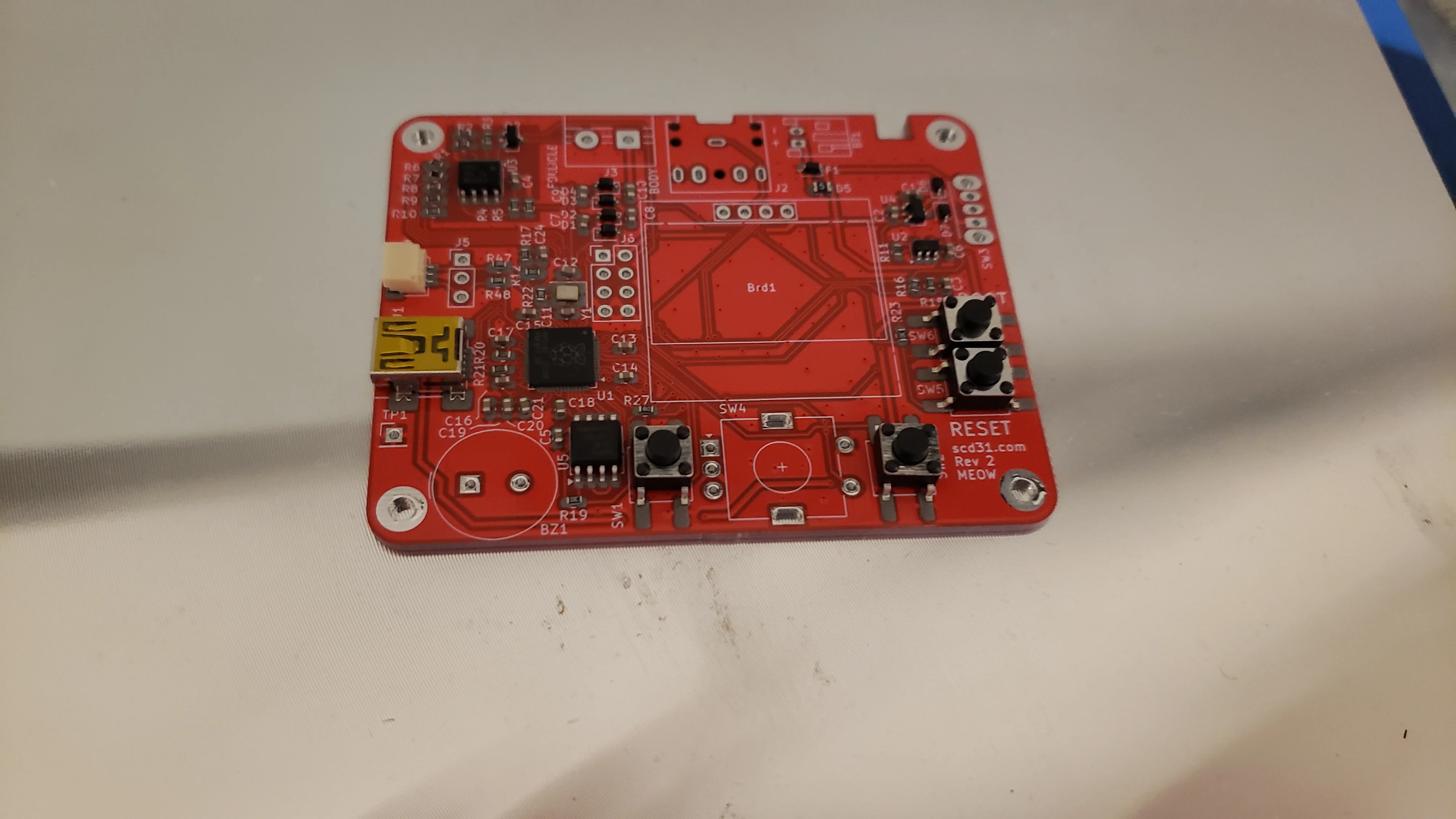
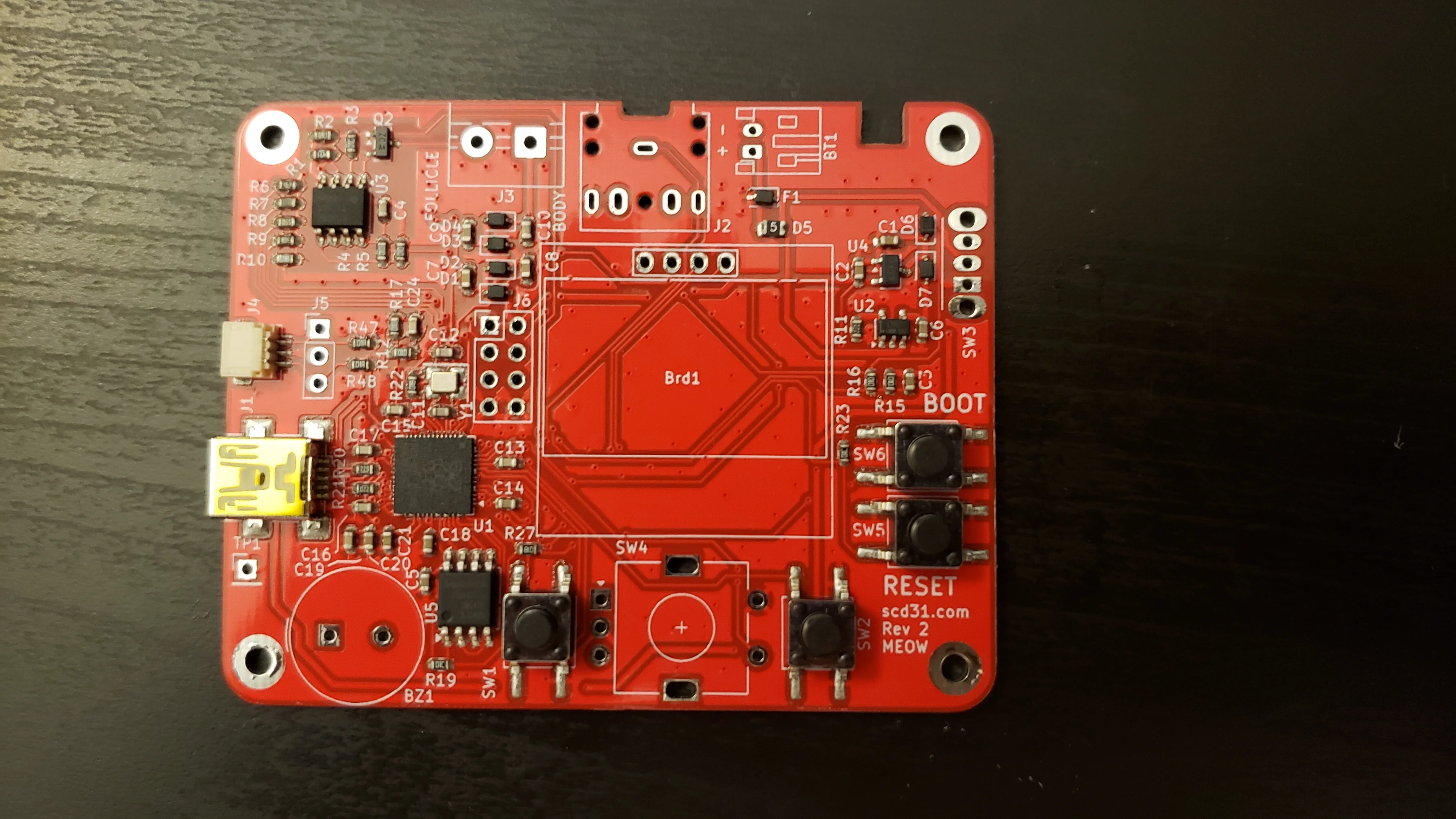
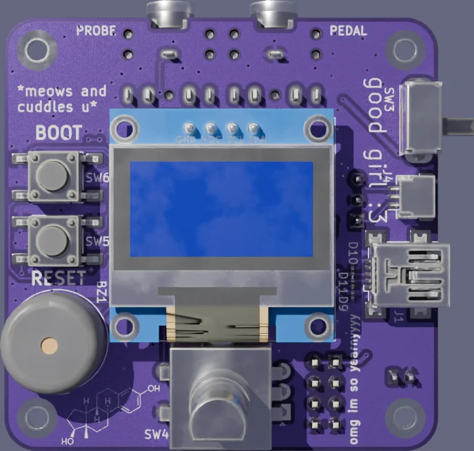
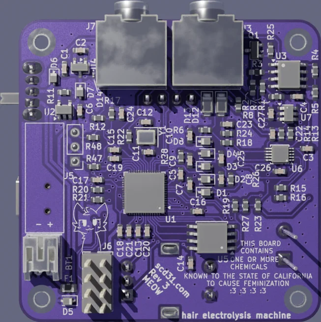
I came up with this:
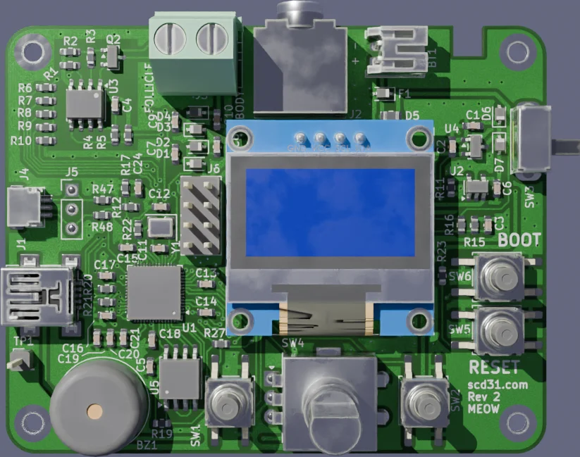
The board architecture is relatively simple. There's a single 3.7 V battery for power, and an RP2040 to run the show. The user interfaces with the device through a single OLED display and rotary encoder. There's also a 3.5 mm jack that connects to the foot pedal. I added some extra buttons just in case, but never actually ended up using them. Aside from this, there are two main pieces that actually enable the hair electrolysis: the charge pump and the current DAC.
The charge pump
The body is high impedance, even though the needle goes below the skin. We need enough voltage to push the current through. Our 3.7 volt battery isn't enough. I didn't want to use a second power source, so we need to boost this voltage.
One of the simplest ways to generate a higher voltage is with something called a charge pump. These are a family of DC-DC converters that use capacitors to move charge around. They're highly efficient and simple. For my board I used a Dickson charge pump:
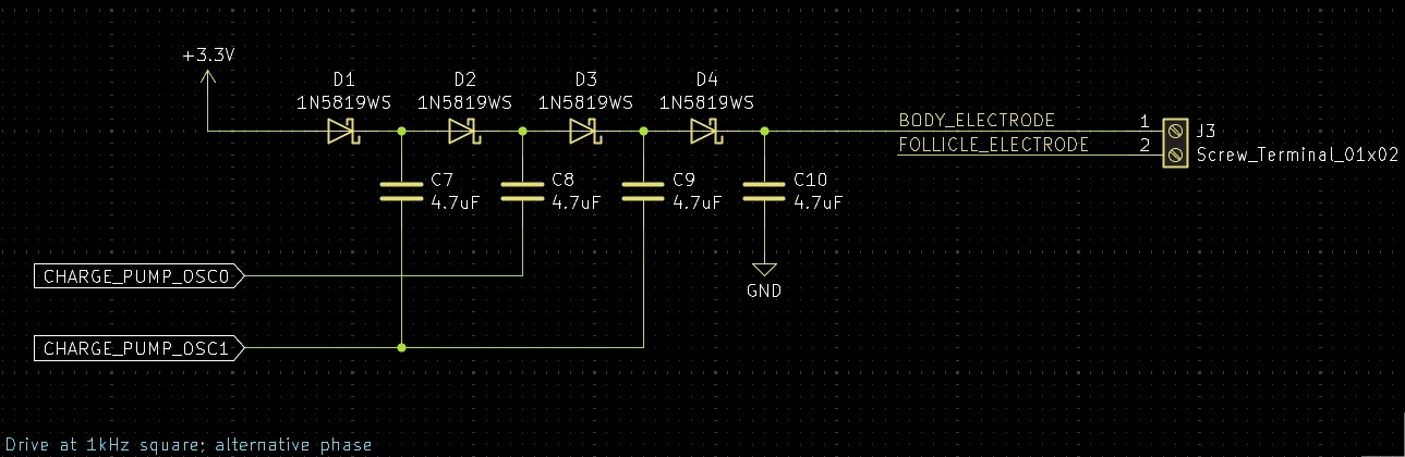
With just a few capacitors and diodes, we can turn 2 out-of-phase PWM signals from my RP2040 into a much higher voltage. I'm using 3 stages to turn my 3.3 volt I/O into a little over 12 volts. Due to the relatively small capacitors and slow switching rate, the circuit is only capable of supplying a few milliamps. This is a great safety feature - even if our own current limiting fails, there just isn't enough power to here to do serious damage.
The current DAC
We have enough voltage and current available to drive the electrolysis process forward, but we need to control it accurately. What actually matters is controlling the current specifically, as that determines how much lye is generated.
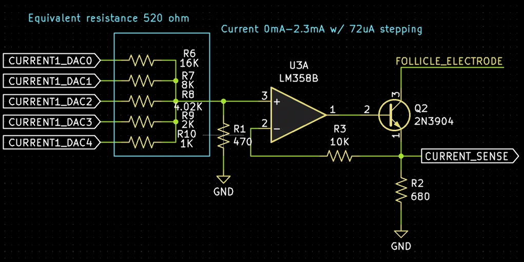
The circuit to do this is fairly simple. We're using a 5-bit resistor DAC as a microcontroller-controlled voltage source. An R-2R DAC would have been better here (i.e. less work to assemble) but this was a total rush-job, as I'll explain later.
The DAC output is fed into an op-amp, which compares it with a sense resistor. The output of the op-amp is fed into a BJT. The result of this is we end up with a current that's proportional to the voltage of the DAC.
Although this is enough to do what we need, I also fed the current sense back into the RP2040 via its ADC. This allows the RP2040 to sanity-check that the supplied current is actually what it requested. For example, if the body impedance was too high, we might not actually get all of the current we expect. It's important that the microcontroller knows the actual value so that it can compute the amount of lye correctly.
For reasons that now elude me, I designed this board as quickly as possible so I could order it. I was so sloppy that I immediately noticed some pretty bad problems. Rev 2 was ordered less than a day later; I was able to combine the orders so it only cost me a few extra dollars. It's a little embarrassing though, especially as I now have a bunch of boards that are totally useless.
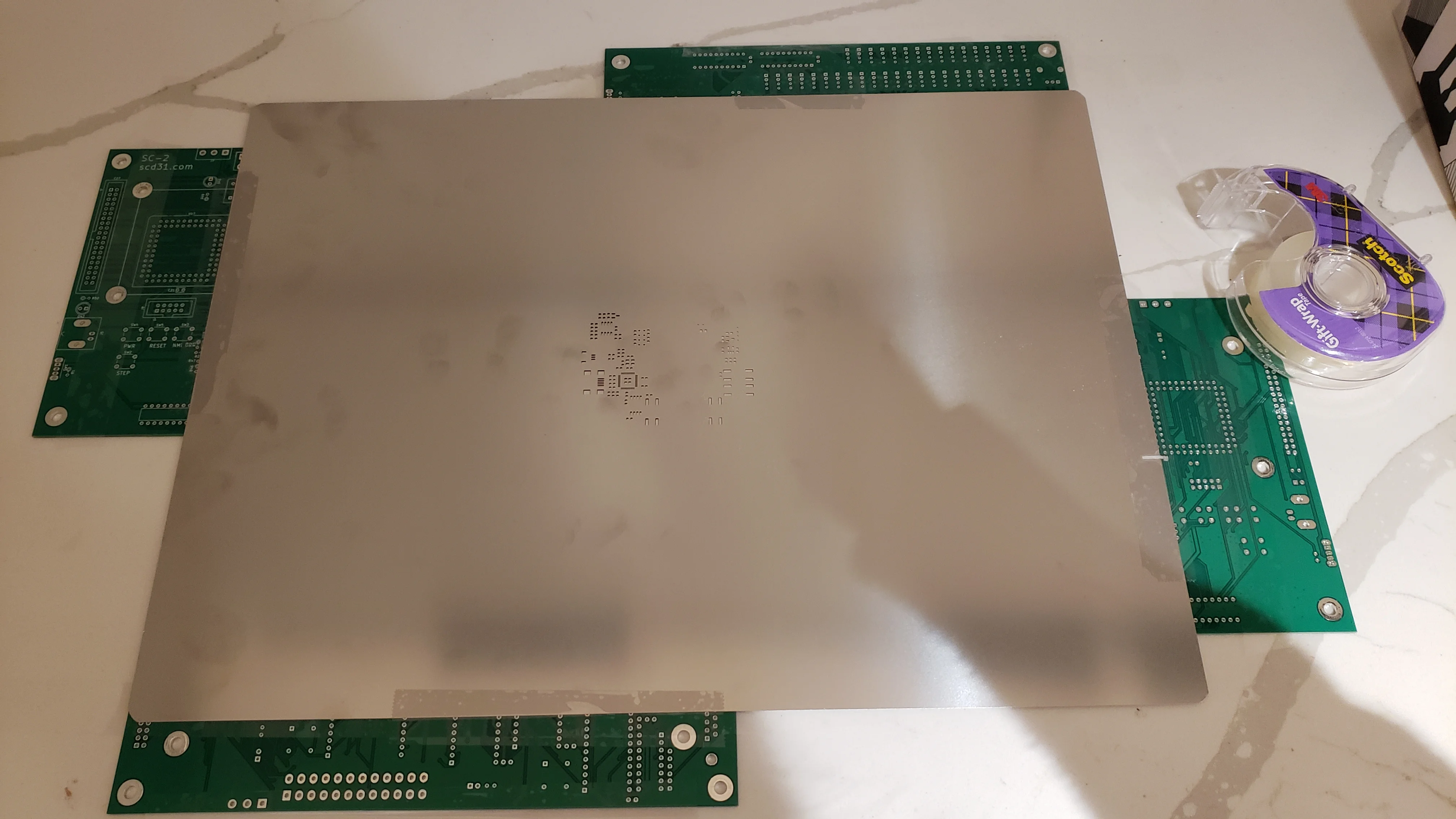
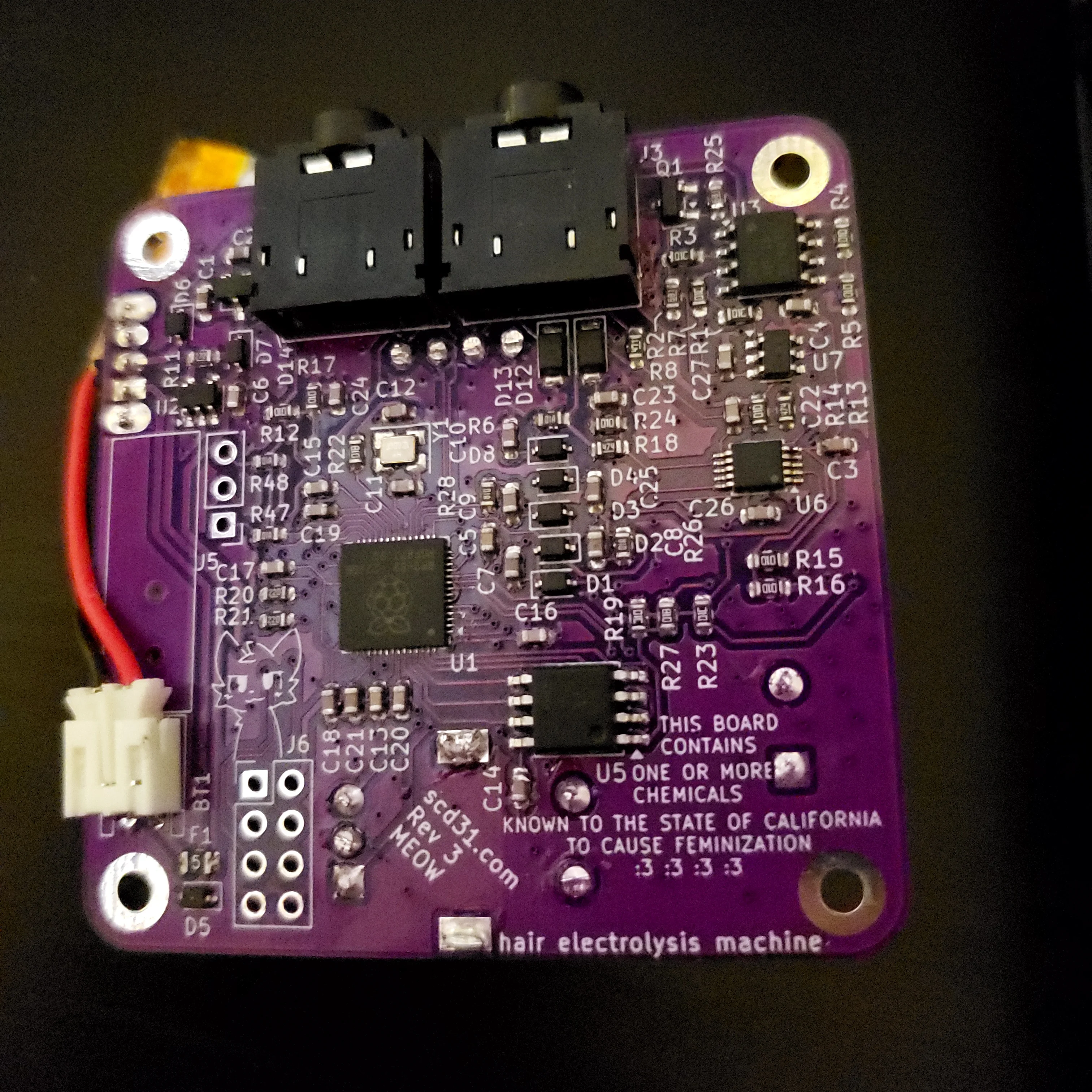
Normally I pay for PCB assembly, because it's so cheap, but this is a pretty low-risk project and I decided to assemble the board myself. I paid a few extra dollars for a solder stencil. This was my first time using one but it made the assembly a lot quicker.
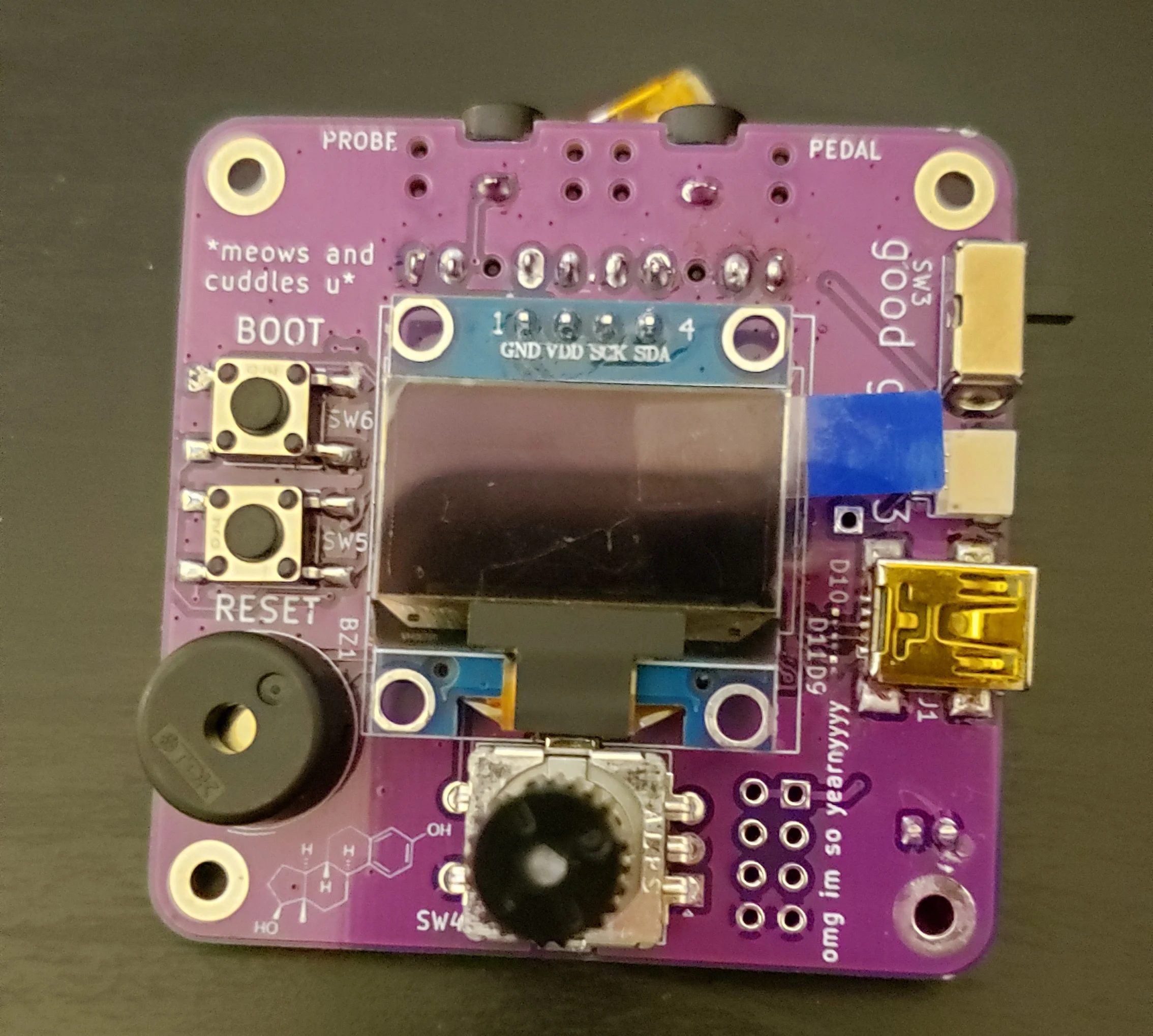
It took a little over a week for the boards to arrive. They came on a Friday and I assembled them immediately when I got home.
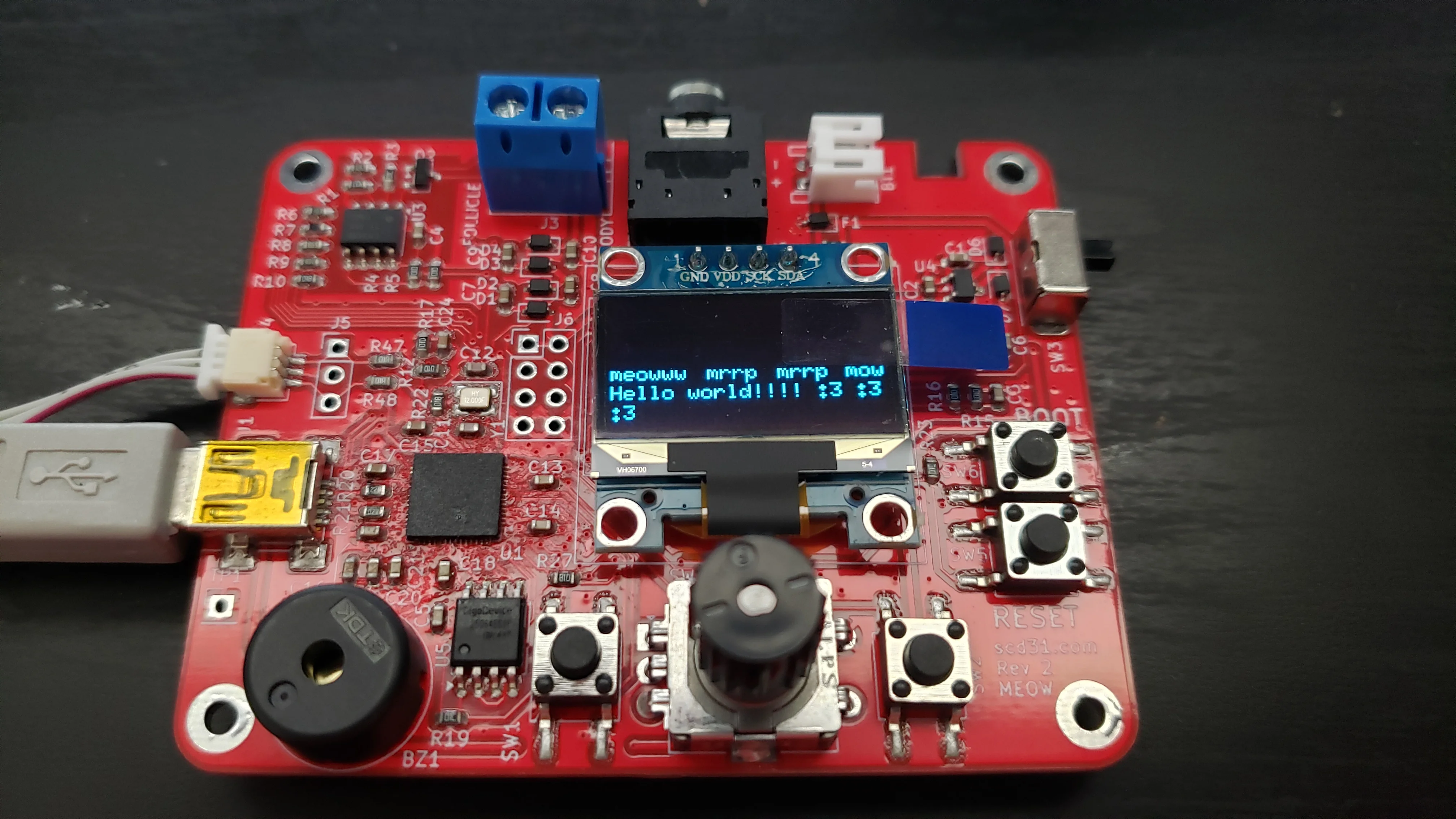
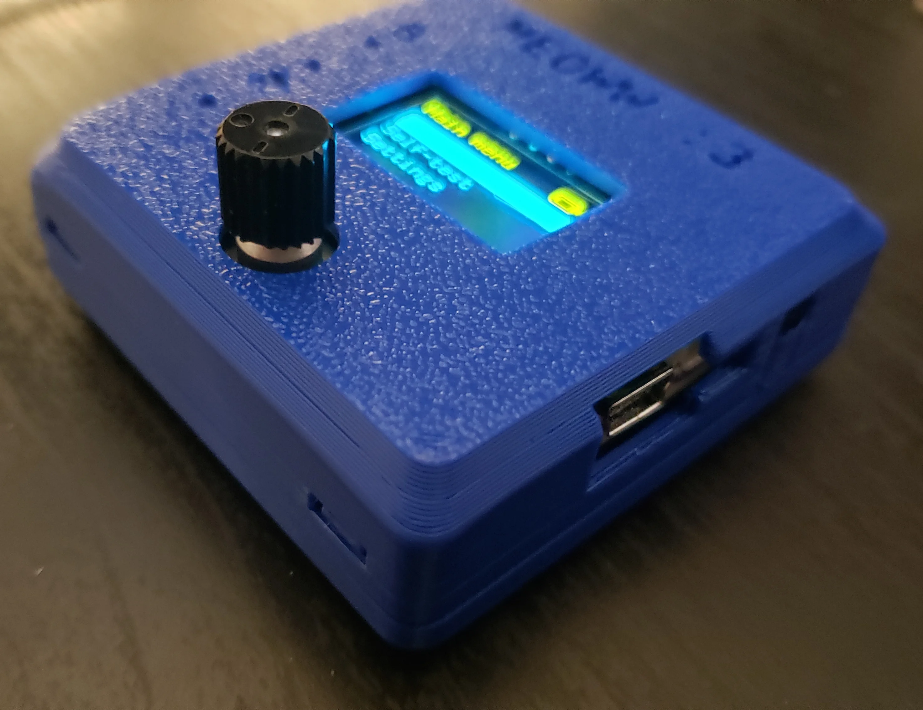
I spent the weekend locked inside writing the firmware. By Sunday afternoon, I had it pretty much done and usable. I could set a target lye level, maximum current, and ramp speed. These are all be stored in flash, so they're remembered between power cycles. I also implemented a self-test feature which allowed me to confim everything worked correctly. The entire thing was powered by a GUI that I built from scratch.
The firmware was written in Rust using the Embassy framework. I'm actually generally an RTIC 1 girlie, but for this project I thought I'd try something new. I was a little skeptical at first, but I actually really like Embassy. Using async for cooperative multitasking actually works really well.
Aside from making the firmware functional, it was also important to make it cute. The board has a piezo buzzer, and I made sure to emit all sorts of beeps and boops when appropriate. My favourite is when running a self-test - it plays a little scale as it sweeps through the current range!
This was the part of the project where I started discussing what I was building with more friends. I found it quite funny how many people asked what I was testing it on - software engineers are so cute with their test environments <3 I of course was testing on myself from day 1. Real bugs are bugs that cause you to risk mutilating yourself :3 (I of course checked things extensively with a multimeter and scope before connecting to my body!)
While testing, I discovered a few hardware problems:
The charge pump was connected directly to the RP2040, and at startup the current draw would be hard on the GPIO. After enough startups, I eventually blew out one of the pins. This caused the output voltage to be lower than expected. I worked around this by supplementing the power source with a cheap power supply. It's not the safest thing ever but it worked for testing. Later, I added some bodge wires to run the charge pump off a different GPIO pin, with current-limiting resistors to protect it from damage.
The current-limiting circuit had a pretty bad problem. Current could leak out through the base of the BJT transistor, which would be incorrectly picked up as supplied current, messing up measurements (and causing the actual current to be lower than the requested current). I was able to bodge a resistor in to at least improve this, but it still wasn't perfect.
There were also lots of little problems. The 5-bit DAC really didn't have enough fidelity, and the RP2040's ADC was absolutely awful. There were errors on the silkscreen from the original rush job. Most egregiously, this included completely swapping two component names! I luckily noticed this during assembly, otherwise I probably would have damaged something.
Even with these issues, the machine was still a huge improvement over the car battery. I could quickly go through and kill off follicles one-by-one. Still, these problems led me to design a new board.
Developing rev 3
Since rev 1 was ordered and pretty much immediately scrapped, the next board was labelled rev 3 (even though I really only considered it to be a second revision). This time I decided the main thing to be mindful of was not rushing.
I fixed all the big problems. The BJT was replaced with a MOSFET, which fixed the current leaking issue. I added some resistors around the charge pump to protect the RP2040. While I was at it, I added another stage to increase the generated voltage to a little over 15 volts. I also replaced the resistor DAC and RP2040 ADC with dedicated chips. Finally, I made a list of every small problem and ensured I fixed all of them.
I also decided to improve the layout of the board. Putting the display on the front made no sense - it took up so much space! I moved it, as well as the rest of the interface, to the back. Most of the connectors followed. This allowed me to squish the board down into a square that was just 53 mm on each side. Despite the smaller size, I took my time and routed traces better than the last revision. Routing is such a relaxing process when you're not rushing!
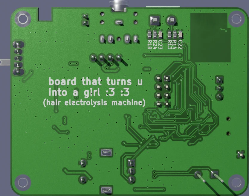
I showed the board design to a friend, but she said it wasn't transgender enough. So I spent another half hour or so improving the silkscreen, and ended up with this masterpiece:
At this point I was technically done, but I decided to sleep on it, do another board review, and then order. I usually like sleeping before doing the final board review - often I pick up on new things I missed before. I also ordered the new components I needed; most I could reuse from the last revision but I did have a few new parts to order.
While I waited for everything to arrive I designed a quick case using OpenSCAD and YAPP_Box. I love parametric boxes for my projects; everything is just a bunch of code!
Rev 3 was a big success over rev 2. The new DAC and ADC were both so amazing - I loved that I could really request exactly the current I wanted, and the ADC was so accurate I could literally watch the battery voltage drop, 2 mV at a time. I have no plans to order a rev 4 in the near future. There's just not much to fix!
Using the machine
By this point I had zapped quite a few hairs and had built up a bit of an intuition about it. One thing I noticed was the environment was very dynamic - once the lye started being produced things changed a lot. For one, the resistance dropped - I could feel this when driving it from the car battery, but the board's constant-current source made it imperceptible. The lye also acts as a lubricant, which makes the needle slide in much easier.
I was initially quite bad and kept missing the follicles, but got better over time. One way I could tell when this happened is when a "mosquito bite" would develop at the insertion site. This wasn't a real bug bite, of course, but it looked almost identical to one. When I properly inserted the needle into the follicle, there would be no bug bite, and instead the lye would leak out slightly.
Demos
Alright, now for what you came for.
Here's a video where I go through all the menus. There aren't a lot but I think it gives you a good picture of how the device is meant to be interacted with. I also go through actually using the device, although instead of using a human, I just use a dummy load. The dummy load is a 470 ohm resistor internal to the device.
And now here's the arguably cooler demo, where I actually use the device to permanently remove one of the hairs on my hand.
It's funny that watching this video makes me squirm more than actually making it did.
The CI/CD pipeline
This isn't super relevant to the actual hardware goals of this project, but I developed a pretty nice CI/CD pipeline for all the hardware stuff. I packaged Kibot for Nix and then created a bunch of Nix derivations for everything. There's one to build the case, one to run board tests (electrical & design rules), one to spit out the files I need to fab the board, and one to render the board. The images in the README actually point to these artifacts, so when I make changes to the board they automatically show up!
Hardware and software people tend to not have a lot of overlap, so CI/CD for boards is fairly unusual. I like the workflow a lot, though. When "compiling" a board means spending real money, having it be repeatable is arguably more useful than a software side project where I can try again for free.
Goodbye, body hair
So yeah, I built a working hair electrolysis machine that's going to save me potentially hundreds or thousands of dollars. I can also do electrolysis on a whim, at home, whenever I have a bit of free time. To me, this seems much more optimal than having to schedule an appointment.
DIY hair electrolysis isn't that unheard of in the transfem community, but I believe this is by far the most advanced DIY machine. I hope the increased automation will pay dividends in saving my time and sanity. Like with all my projects, I've open sourced it. I of course can't recommend reproducing it - it's basically a medical device designed by an idiot - but I hope the design is valuable to someone.
I'm thinking about building a blend electrolysis machine next. I'm always itching for a good RF project. But who knows, there's a lot less data available there, and a lot more to mess up, as I've mentioned.
The hardware, including the schematics, board design, case, and pen, live here.
The firmware that runs on the device lives here.