Some time ago, I saw this video by DIY Perks where they make artificial sunlight at home with a 500W LED and a gigantic (1.2m) parabolic reflector. I've been fascinated by this project ever since, and I wanted my own.
Over the past year or so, I finally took the time to work on a similar project, but I had the idea for a different design. The issue with the parabolic reflector is that it takes a huge amount of space. Could I do something similar, but with a less bulky design? This is the story of my first attempt at this project - version 1 so to speak. Perhaps there will be a version 2 in the future. Enjoy the read!
My idea - as others have had I'm sure - was to use an array of lenses laid out as a grid. Then, instead of a single light source, I would use a grid array of multiple LEDs, one per lens. In my mind, this would have two major advantages:
- Less bulky. The size of the device would be determined by the focal length of the individual lens elements, and because each would be small, the focal length could be small also, while maintaining a decent f number.
- Easier thermal management. Multiple light sources could be regular low power LEDs which wouldn't need special cooling. There would just be a lot of them, spread out over the entire device surface.
Over the course of this project, I also intended to teach myself some manufacturing and 3D design, as I don't have any experience doing any of this. My background is software, and as you'll see I took a very software heavy approach to this. It was all a long learning journey for me, but in the end I used:
- Mostly build123d for CAD modeling, with some FreeCAD for final assembly checks and some experiments here and there - including with the cool OpticsWorkbench.
- KiCad for PCB design.
- Custom python code for simulating light and optimizing the optical system. (This custom code eventually became an entire open-source project for optimization-based optical design)
- JLCPCB for printing and assembling PCBs, and for manufacturing aluminum and plastic parts with their CNC service.
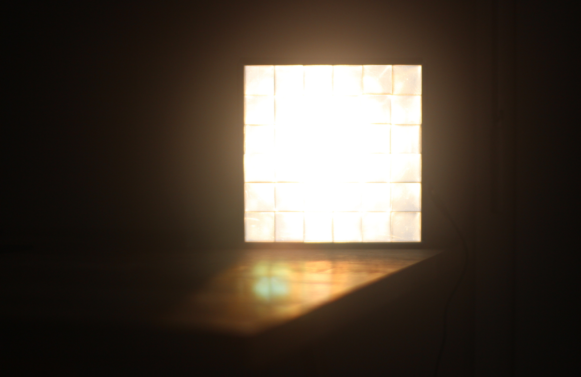
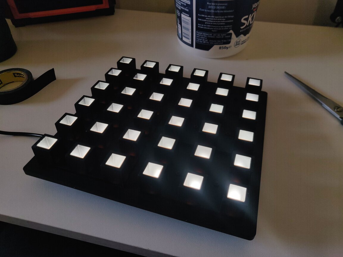
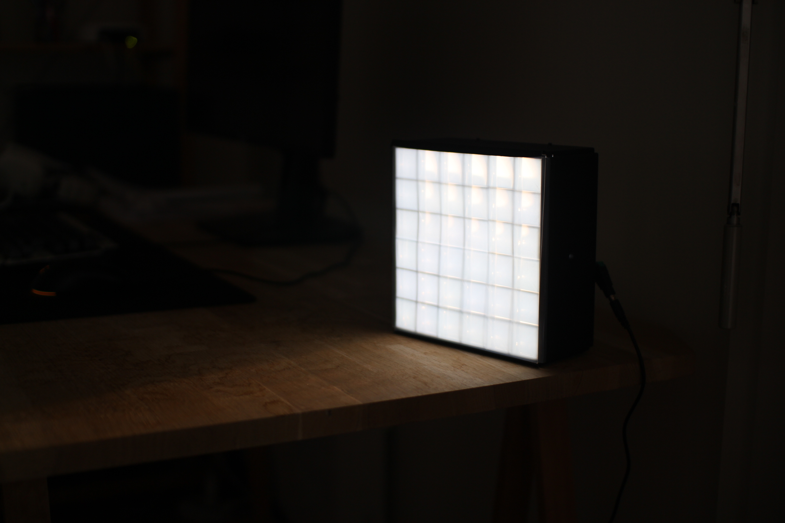
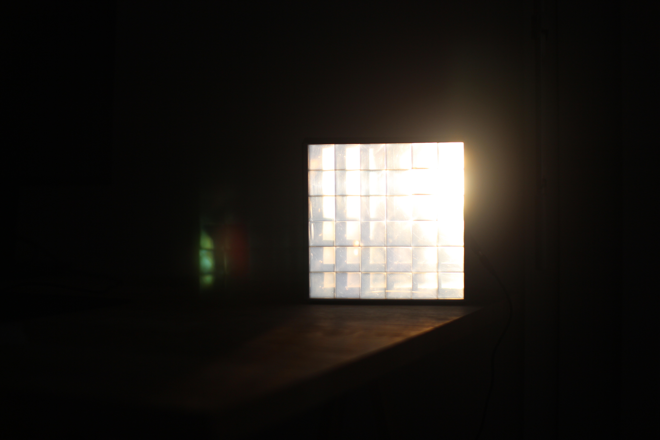
TL;DR: I did it! Here is the finished device sitting on my desk today, at night:
And here it is during the day (much less impressive!)
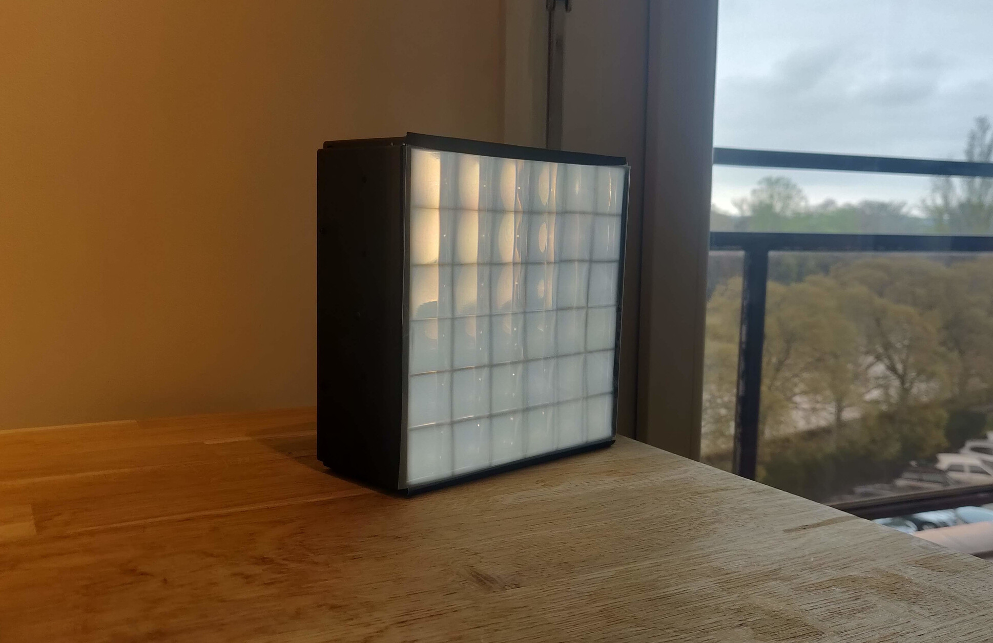
Beware it's kinda hard to take good pictures of it, and I don't have the best photo gear. Here's also a video: (at night)
Kinda cool that you can see a lens flare effect in the shape of the lens grid array.
Technical specs
Mechanical:
- Lens square side length: 30mm
- Effective Focal length: 55mm
- Array size: 6x6 = 36 LEDs
- Total size: 180x180mm
Parts:
- Lenses: 1 biconvex lens array, 1 plano-convex lens array - custom made out of PMMA acrylic, CNC fabrication with vapor polish finish @ JLCCNC
- LEDs: LUXEON 2835 3V -- Ref: 2835HE. CRI: 95+, color temp: 4000K, 65mA.
- PCBs: Custom design
- Mounting hardware: custom design - aluminium 60601 for the CNC parts and mate black resin for the 3D printed parts
- Rayleigh diffuser: waterproof printing inkjet film
General design and sizing
To create artificial sunlight, you need four ingredients:
- Parallel light rays. The sun is so far away that light rays emitted from a point on the surface of the sun reach us essentially parallel. This is not to say that all light rays coming from the sun are parallel, as it still has a 0.5 deg apparent angular size. But they need to be pretty straight. Any light coming from an artificial light source like an LED will be going in all directions, so some optics is required.
- High color quality. A good indicator to look for on a datasheet is the color rendering index (CRI). 95+ is recommended to achieve a good effect. I'm sure there's more color science you could get into, but CRI is a great start for off the shelf parts.
- Rayleigh scattering, or an imitation of it.
- A LOT of power.
Light intensity is the most important sizing constraint, so let's look at it first. Now, the sun is very bright. Like, ridiculously bright: around 100,000 lux. To achieve this with LEDs is by no means impossible, but it's a challenge. For this first version, I thought that targetting 10,000 lux would be quite enough because it would reduce the power consumption a lot for a first prototype, and also brightness perception is logarithmic. So one tenth of the intensity is really, perceptually, almost the same as full brightness. (In the end, I estimate my design only effectively achieved something between 1000 and 10000 lux).
The general grid based design of this project really has two variables:
- the individual LED light output, in lumens
- the individual lens surface area in mm²
After some research, I think values between 30 to 130 lumens are typical for high CRI surface mount LEDs. So, assuming this is what we are working with, what is the required lens size to achieve the brightness of the sun?
We have to assume some non perfect efficiency for collimating the light. This will never be 100%, and in fact may be quite low if the focal length is high, because a lot of the light will be hitting the side walls instead of reaching the lens. The lens itself will also be absorbing some light. So taking a wild guess of 0.5 for the overall optical efficiency, and taking three lumens value of 30, 80 and 130, we get this plot:
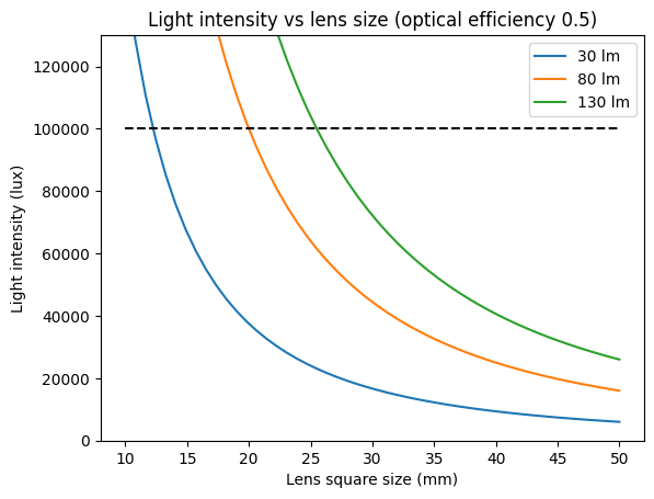
With that in mind, I selected 30mm as my lens square side length. Presumably, this would be small enough to achieve some effect, but not too small to make the lenses too hard to make.
Lenses
Focal length, and the lenses shape in general, is the next design consideration. The goal is to have perfectly parallel light rays. In theory, with a perfect point source and a perfect lens this is easy. Put the light source at the lens focal length, you're done. In practice, a lot of things make it harder to achieve with a lens. (This is where the parabolic reflector design is superior to a lens).
- A LED is not a point source
- A lens will not have perfect optical performance (i.e. aberrations)
- Mechanical reality of the device means that positioning and orientation will not be perfect
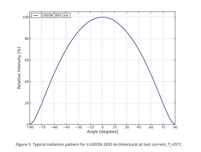
- A LED radiation pattern is not isotropic, meaning intensity will be greater at the lens center
This is the radiation pattern characteristics diagram from my LED datasheet:
I wrote some custom python code to simulate the optical system I had in mind, and find the best lens shape using numerical optimization. (This code eventually became an open-source project: torchlensmaker) After a lot of experimentation, I settled on a 2 lens design:
- Lens 1: Biconvex parabolic lens
- Lens 2: Planoconvex parabolic lens
The effective focal length of this two lens system is about 55mm. Focal length is a key design parameter, and here I feel like more experimentation is needed. It's a big tradeoff consideration and has a huge impact on the system design. It impacts:
- The curvature of the lens surface, which is a key manufacturing point (you want to minimize curvature for manufacturing, which means maximizing focal length)
- The optical efficiency of the system due to the led radiance pattern (here you want to minimize focal length, to gather more of the emitted light)
- The device thickness (here I wanted a not-too-thick device, so to minimize focal length also)
I used a two lens system mostly to reduce the surface curvature of the lens arrays. This reduces the manufacturing cost by a lot. High curvature lenses are more expensive in general, and this grid array design means that a high curvature lens will create sort of "valleys" in between the lenses. Because I was targetting CNC manufacturing, this is to be minimized to get a design that's even possible to machine.
This is the optical simulation I had at the time I finalized the design and ordered the lenses. (Since then my simulation code has improved and I could likely do much better modeling today using the latest version of torchlensmaker):

With some custom build123d code I was able to make the two lenses 3D models by stacking the lenses in a grid pattern and adding edges for mounting:
What's really cool using build123d for 3D modeling, is that I can just change a python variable to change the size of the array, of the thickness of the lens, of anything else really. It's all parametric out of the box because it's regular Python code! This makes exploring the design space very efficient. I've never done 3D modeling any other way, but I can't imagine ever not having the power of programming with me if I ever do it again!
I had the lenses manufactured out of PMMA acrylic at JLC with a vapor polish finish. Total cost for the lenses was about 55€ which is really not bad!
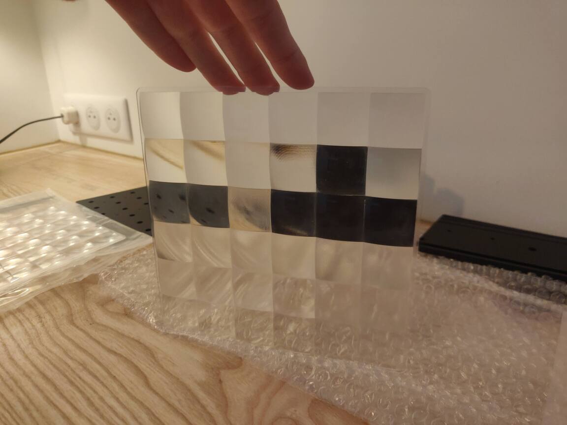
One of the two main lens array, built by JLCCNC:
LEDs
I really wanted to use the 3030 G04 from YUJILEDS, but it's only sold on 5000 units reels that cost $1000 a piece... maybe for version 2 I will upgrade to those. For version 1, I settled on LUXEON 2835 3V. They are about 3 times less bright than the YUJILED, but they have good color rendering and the SMD package I was looking for. And importantly, the minimum order quantity was only 50 at JLC global sourcing.
In the version 1 design, the grid is 6x6 which means 36 LEDs total.
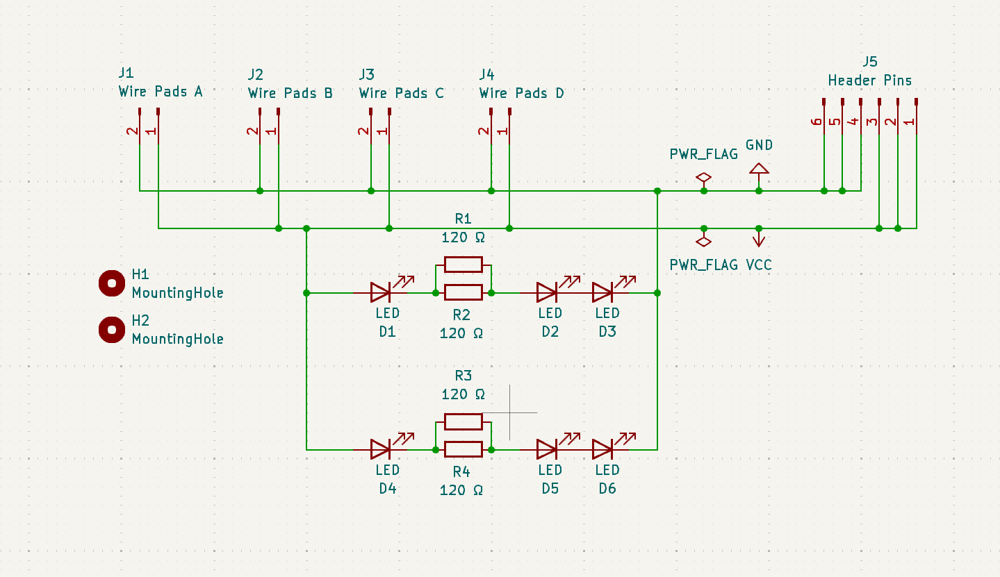
PCBs
I designed a custom PCB with KiCAD. Each PCB holds 6 LEDs which are laid out as 2 segments of a 12V led strip in parallel. This allows to use a standard wall plug 12V power supply.
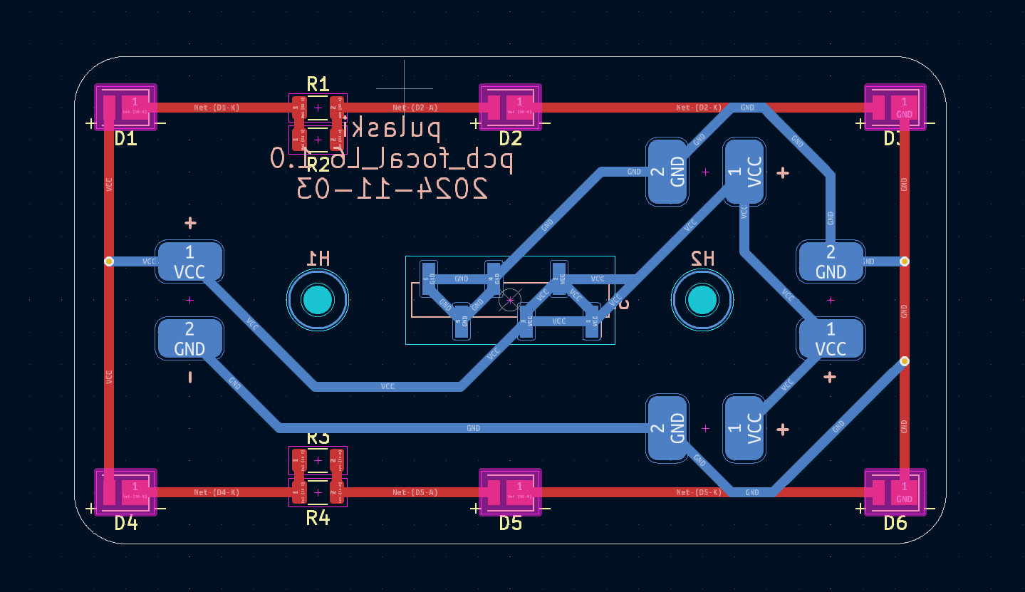
The mechanical role of the PCB is very important in this design. Not only does it distribute power to the LEDs and regulate current, it also precisely positions the LEDs at the lens focal point. For this, exporting the PCB 3D model and importing it into FreeCAD was very useful to check that everything fits together: the PCB in the aluminum support baseplate, the holes on the light hoods, etc. My Python code exported the precise LED coordinates which I could input into KiCad's layout editor.
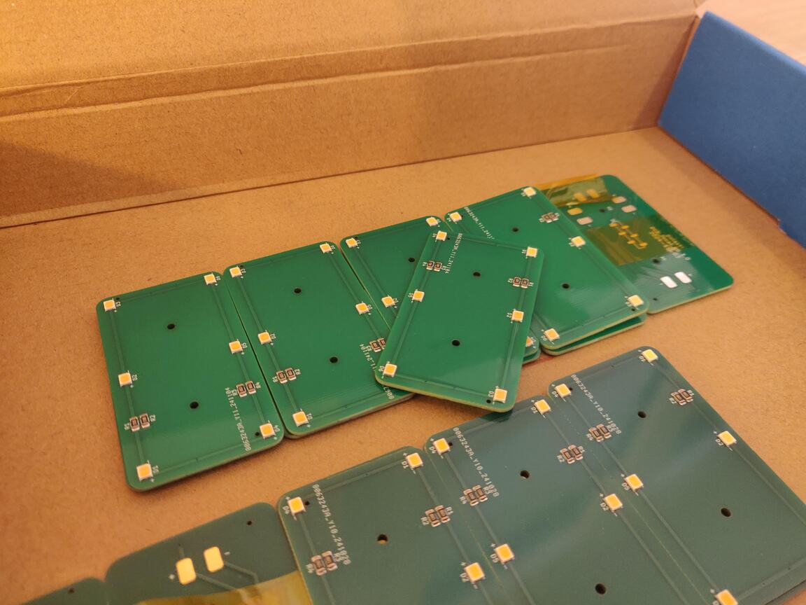
I had the PCB printed and the components assembled by JLCPCB. It's very very cool to design an electronic board on your computer and get it fully assembled in the mail a few weeks later - no soldering required! (for this step anyway).
Mechanical mounting parts
To mount everything together I designed 3 parts:
- A baseplate, to hold the PCBs and the side walls. The PCBs are fitted below the baseplate, and light goes through holes drilled into the baseplate. There are also partial holes to allow for the thickness of the SMD resistors mounted on top of the PCBs, and finally two mounting holes per PCB. This is why it has so many holes :)
- Side walls to hold the lenses using grooves in which to insert them, and a larger groove to secure in the baseplate. The baseplate side holes are threaded to support M2 screws securing the base of the walls. Again, JLCCNC did the drilling and threading of the holes at a great price.
- Light hoods, a rectangle block with rectangular holes. It sits on top of the PCB to shape the light coming from each LED into a cone (or really a four sided pyramid). This is to make sure light from a given LED only reaches its matching lens on the lens array, and no other. Bleed light is inevitable, but at least this prevents direct leakage.
The hoods were 3D printed out of black resin, the walls and baseplate were CNC cut out of Aluminum 60601.
I'm not a mechanical engineer so this process was... trial and error. Still the result is working so I'm quite happy with that. For a possible version 2, there's a lot I'll change in the mechanical design. But apart from the one design flaw I was able to fix manually with a drill (more on that below), everything fit together quite well on the first try.
Rayleigh scattering
The final ingredient is Rayleigh scattering. This is the physical phenomenon that makes the sky look blue, and it's important to achieve a convincing effect. In the DIY Perks video that inspired this project, they used a home made liquid solution with suspended particles of the correct size for Rayleigh scattering. Not super practical and I really wanted to find another solution (get it?). Thankfully, some time after the original video, someone on the diyperks forum discovered that inkjet print film achieves a very similar effect. A quick trip to a local office supply store was all I needed here! Amazing discovery.
I didn't anticipate this step during the initial design phase, so the film is simply cut to the correct size and secured with black electrical tape.
Assembly
After a few weeks of design work, and another few weeks of waiting for the parts to arrive, it was finally time for assembly!
On top of the individual 3D models made with build123d, I had a final assembly FreeCAD model with all parts fitted together, including the lenses:
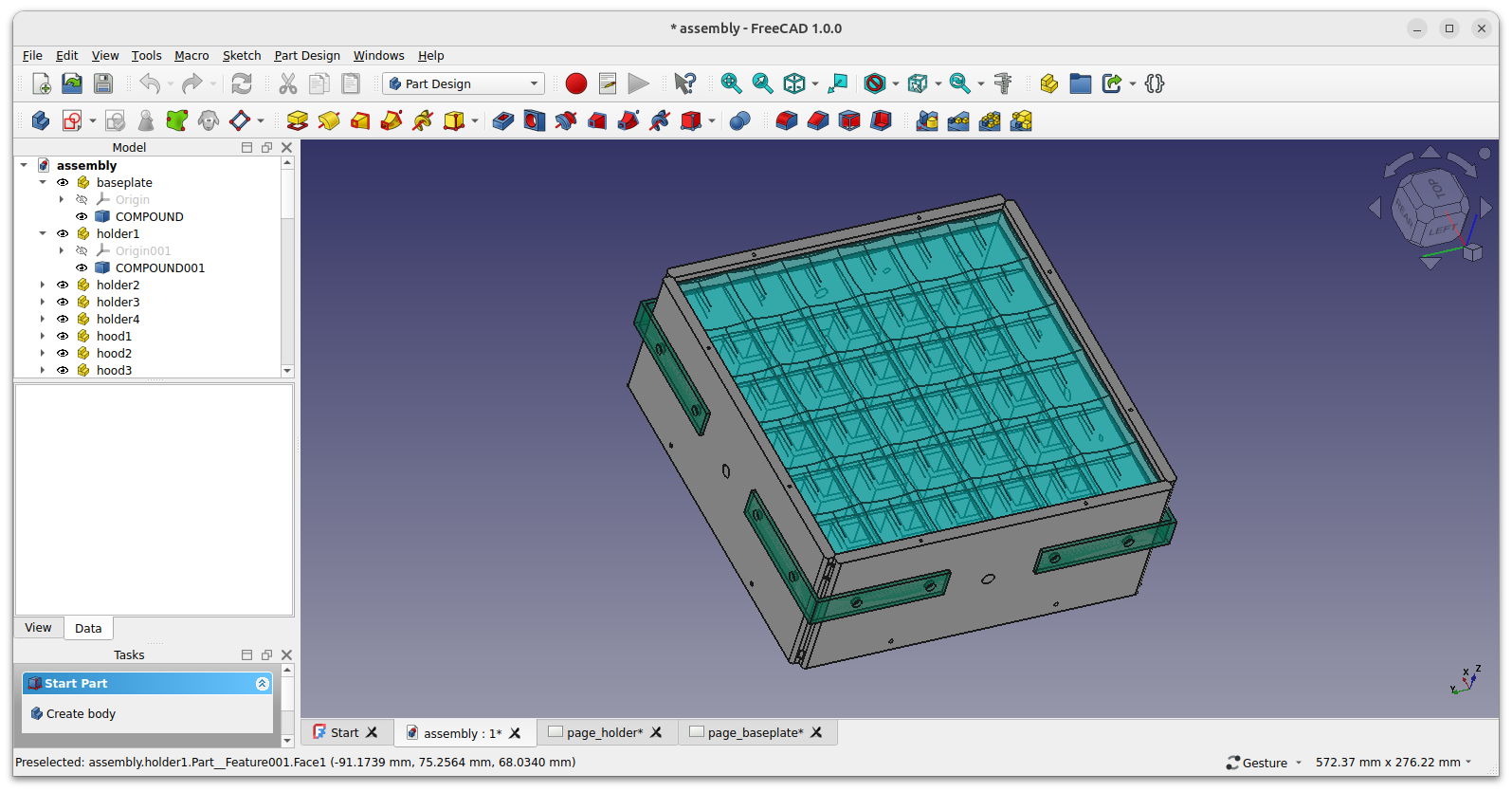
Note the green brackets that I initially planned to use. When actually assembling the walls to the baseplate, the solidity of the formed box was very high, I decided to drop the brackets entirely. This is why some extra unused holes remain on the side walls.
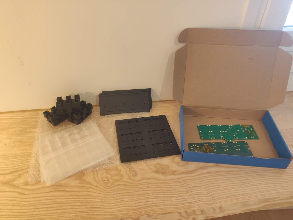
This is all the parts just after unboxing (excluding the inkjet film, solder tin, screws, power supply, wiring, electrical tape):
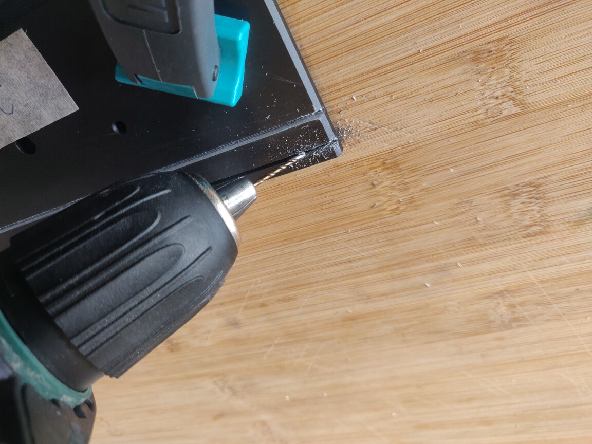
The only real design flaw was insufficient width of the grooves that hold the lenses. The lenses have an edge thickness of 1.2mm, which I had intended to fit into a 1.22mm groove. Turns out this was not enough, probably due to a combination of manufacturing tolerance and additional thickness added by the anodizing black matte surface finish of the aluminum part. The lenses didn't fit into the grooves!
I don't have a very advanced tools at home, so my best solution to this was making the existing grooves wider by hand using a power drill. I bought a 1.5mm metal drill bit and achieved a decent result by doing 4 to 5 passes per groove. This took about 2-3h in total because I had to move the bit quite slow and could only machine about 1/4th of each groove depth at a time by moving the drill bit slowly accross, and there are 8 grooves total.
Here's some more pictures of assembly below.
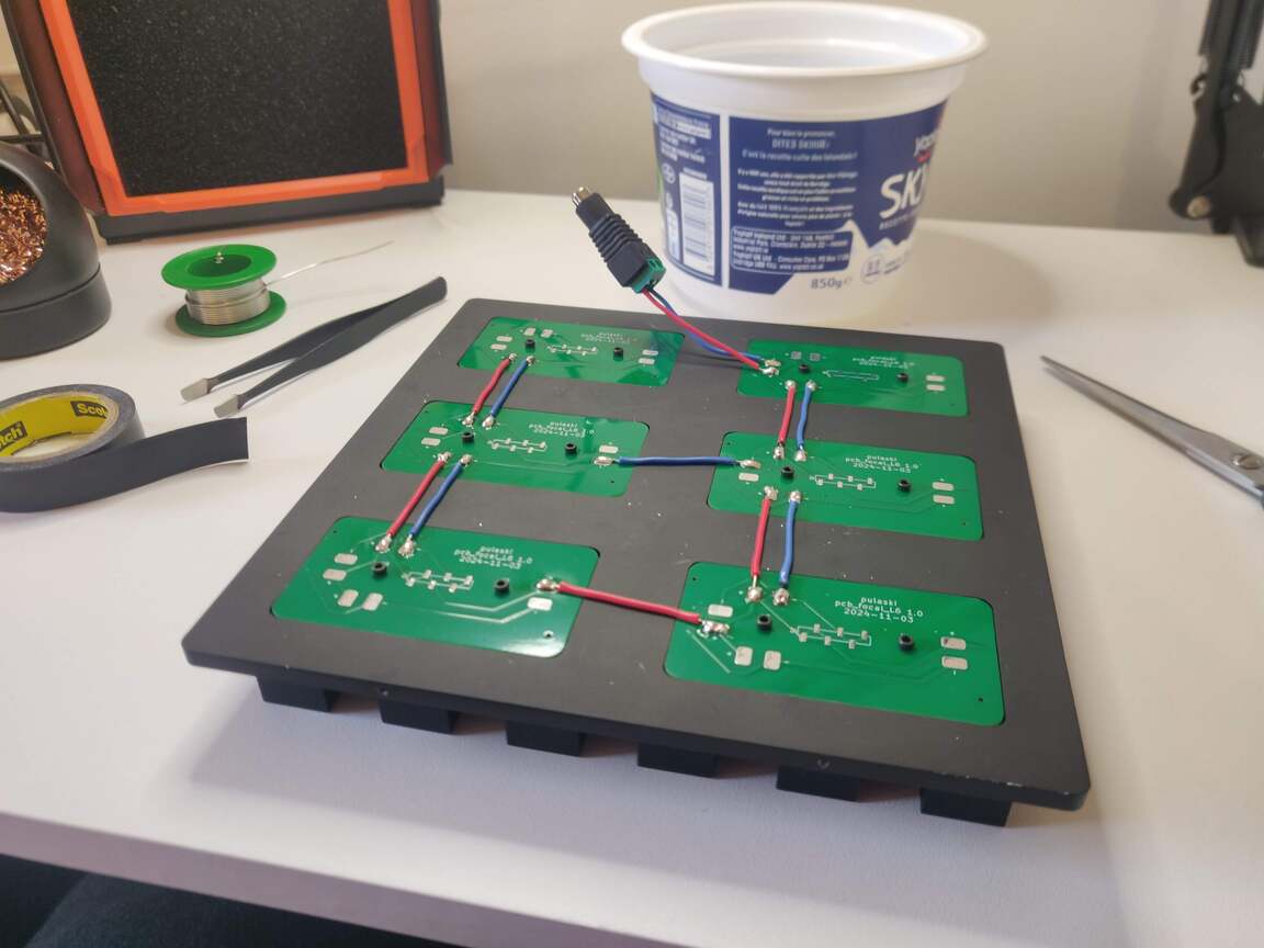
The back side after soldering wires to the PCB power pins and a socket for the 12V power supply. The PCBs and hood pieces share a common mounting hole so only two screws per PCB-hood pair are used.
The front side of the baseplate + PCB + hoods assembly, but without the lenses, powered on. Don't look at it directly :)
It's interesting to note that in the picture above, all of the light you can see from the LEDs is actually "bleed light" and not useful light. None of the light visible above is the light that's intended to go into the lens and produce the sunlight effect.
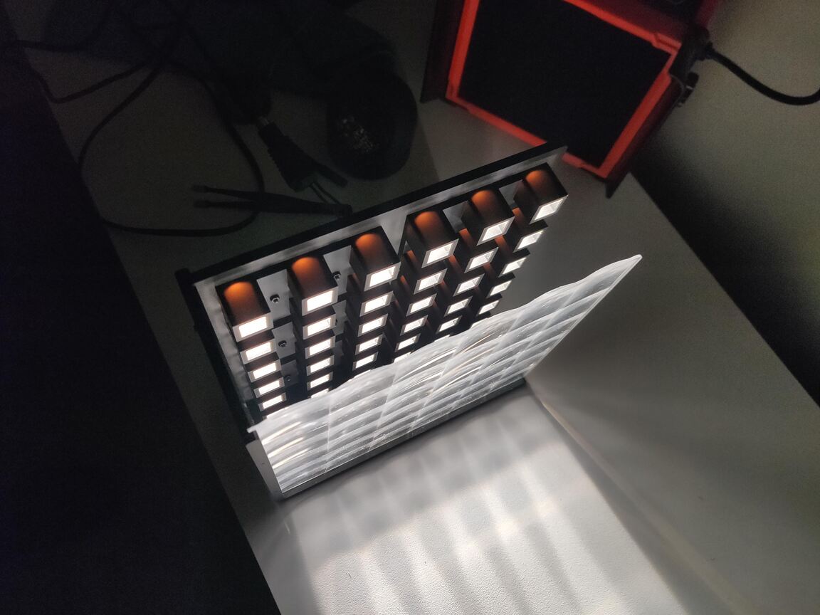
Testing with partial assembly of the walls and only 1 out of the 2 lenses:
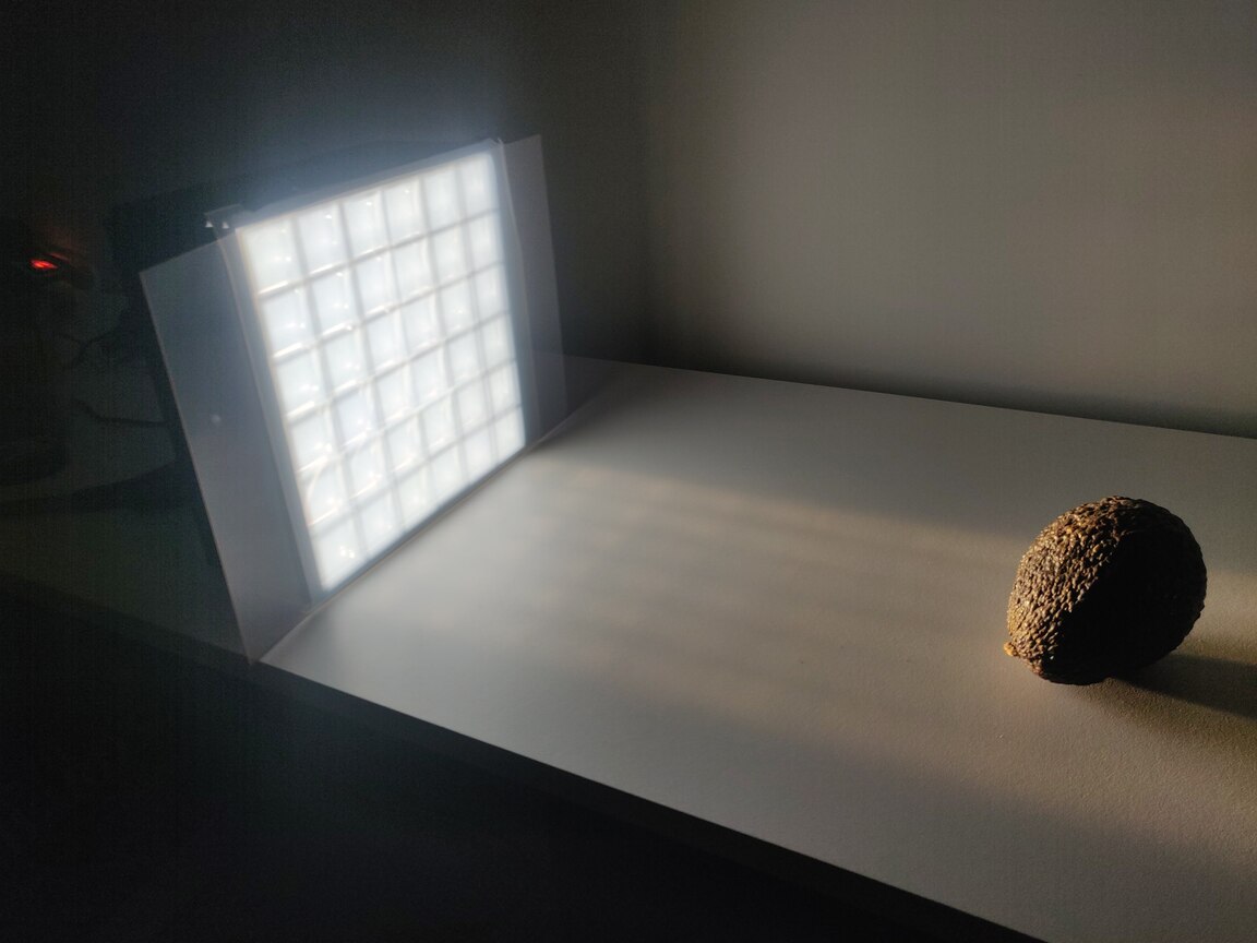
Testing the inkjet film layers with an avocado as a subject. I settled on using two layers of the inkjet film for the final build:
Cost
Overall I spent around 1000€ on this project. But this includes cost of tools I was missing, prototype parts that I had manufactured but discarded, bulk orders for parts like LEDs and PCBs which had a minium order quantity above what I need for 1 unit, and various supplies like screws, etc. The actual raw cost of parts only, without shipping, to build the final unit is hard to estimate. But I would say around 300€. The most expensive parts are the CNC parts (PMMA lenses and the aluminum baseplate and walls) accounting for about 2/3rd of the total price. The rest (PCBs, assembly service, LEDs, 3D printed plastic parts) was quite cheap.
Conclusion
As I write this the final piece is sitting on my desk and producing a pleasant soft white glow. It's definitely nice, and I'm very proud of the result - especially because this was by far the biggest build project I have ever done.
Thanks to this project, I've learned a ton about PCB design, electronics and CNC manufacturing and optics. I even got so far down the side quest of learning optics that I started an open-source python project for modeling geometric optics.
So, is it convincing as artificial sunlight?
My honest answer to that is: partially. The geometric effect of the light source appearing at infinity works. As I pan and tilt my head from side to side, the illusion of light coming from way far behind the object is 100% a success. On top of that, if you look at it while moving your head into the light beam, my eyes get surprised - almost hurt - by the sudden intensity jump. This indicates that collimation is good and you can sort of see it in the video at the start of this post.
However it's apparent that it's simply too weak. Don't get me wrong, it's still bright. I can't look at it directly without sunglasses, and honestly it's really hard to take a good picture of it because the contrast between the light it emits and the outside of it is very high.
Another downside is that I can definitely make out the grid of lenses, as the intensity pattern clearly reveals the grid shape. This is quite a minor downside and not really unpleasant, and I'm sure it could be improved upon.
If I were to ever work on a version 2, I would focus on:
- More power. My feeling is the light output needs to be 3 to 5 times stronger to get any closer to a convincing effect, and it's not crazy to aim for as much as 10x brighter than this prototype.
- More surface area. This prototype is 18cm x 18cm. So you only really get the effect if you are able to sit with the produced straight beam of light, which is quite narrow to resemble any kind of "fake window". A future version would need to be 2 to 4 times wider in my opinion.
- Better optical design. I still think a refraction based design is possible, but it requires very precise optical design and mechanical tolerances. My feeling is that a refraction based design, especially as a grid, is very sensitive to positioning and orientation of parts. I lack mechanical engineering skills in this area.
However there are some really encouraging things that I really like about this grid based, refractive design:
- It's scalable. If I had built 4 identical items, I could literally stack them on top of each other and get more surface area. The "bezels" would be only 5% of the total light emitting area, and I'm sure this could be lowered. I also like that the inner design calls for repeated elements, as this introduces some economy of scale, even at the prototype level. The only part that's not trivially scalable is the lens grid. Maybe it could be injection molded for very large scale production, or for medium scale you could come up with a way to tile multiple lens grids into a larger overall grid pattern, adding some thin bezels for mounting.
- It's compact. The total size is 19cm x 19cm x 9cm. This is quite compact for a 5cm focal length and an effective lighting area of 18cm x 18cm. Reflective designs like the DIYPerks video or commercial products like CoeLux do not achieve this form factor.
- Thermal management is better by design. This is not really something I got into for this design, as it's quite underpowered. The whole thing runs comfortably on a 12V / 3A wall brick power supply. But this design offers great margin for scaling up because there isn't a single light source to cool down, but a number of LEDs proportional to the surface area. I suspect the main thermal issue when scaling up would be the cooling of the power supply itself, not of the lamp.
As final thoughts, let me talk about the software heavy approach I had for this project. It's awesome. If I was starting a manufacturing company today, I would do it all code based. PCBs, 3D models, assembly, testing... I want code everywhere. The power of changing a parameter and having the entire design updated with a single script it so good. Run a script and get all the production data including GERBERs, BOM, 3D models, mechanical schematics, technical diagrams, automated tolerance and electrical checks... absolutely no manual steps between changing a design parameter and ready to send a new order to manufacturing. The PCB and CAD space is even evolving to use proper CI/CD tools which is really exciting.
I don't know if I'll ever have the time to work on version 2 of this project, but it was great fun anyway! And now I have a cool unique lamp. Thank you for reading!