In the 1970s, floating-point arithmetic was a mess. Computer manufacturers had a dozen incompatible arithmetic standards. Moreover, floating-point systems were designed around hardware simplicity rather than mathematical rigor, leading to problems with numerical stability. This changed when Intel introduced the 8087 floating-point coprocessor chip in 1980, designed to be as accurate as possible, even in the corner cases. The 8087 became popular because it could be installed in the IBM PC, making floating-point operations up to 100 times faster in applications ranging from spreadsheets to CAD. But more importantly, the 8087 became the floating-point standard used by most computers today.
The 8087 implemented its instructions in complex low-level code called microcode.
I'm part of a group, the Opcode Collective, that is reverse-engineering this microcode, and I've recently made some progress.
In this post, I examine the microcode for one of the 8087's instructions—FSCALE—and describe how this microcode works.
The FSCALE (Floating-point Scale) instruction provides a quick way to scale a number by a power of two, much faster than a multiplication.
I figured that FSCALE was a simple, almost trivial instruction that would be straightforward to understand and explain.
Spoiler: it is not simple. FSCALE uses over 140 micro-instructions and three levels of subroutine calls to handle many special cases.
But the FSCALE microcode illustrates many interesting parts of the 8087, such as the shifter, the adder, and the exponent converter, and also reveals a
hidden feature of the 8087, so hopefully you will find it interesting.
To explore the microcode, I opened up an 8087 chip and created a high-resolution image with a microscope. The large microcode ROM is in the center, holding the 1648 micro-instructions that control the chip. The microcode engine on the left steps through the microcode, handling jumps and subroutine calls. The bottom half of the chip is the "datapath", the circuitry that performs floating-point calculations; it is split into a 16-bit datapath for the number's exponent and a 64-bit datapath for the number's significand (also known as the fractional part).
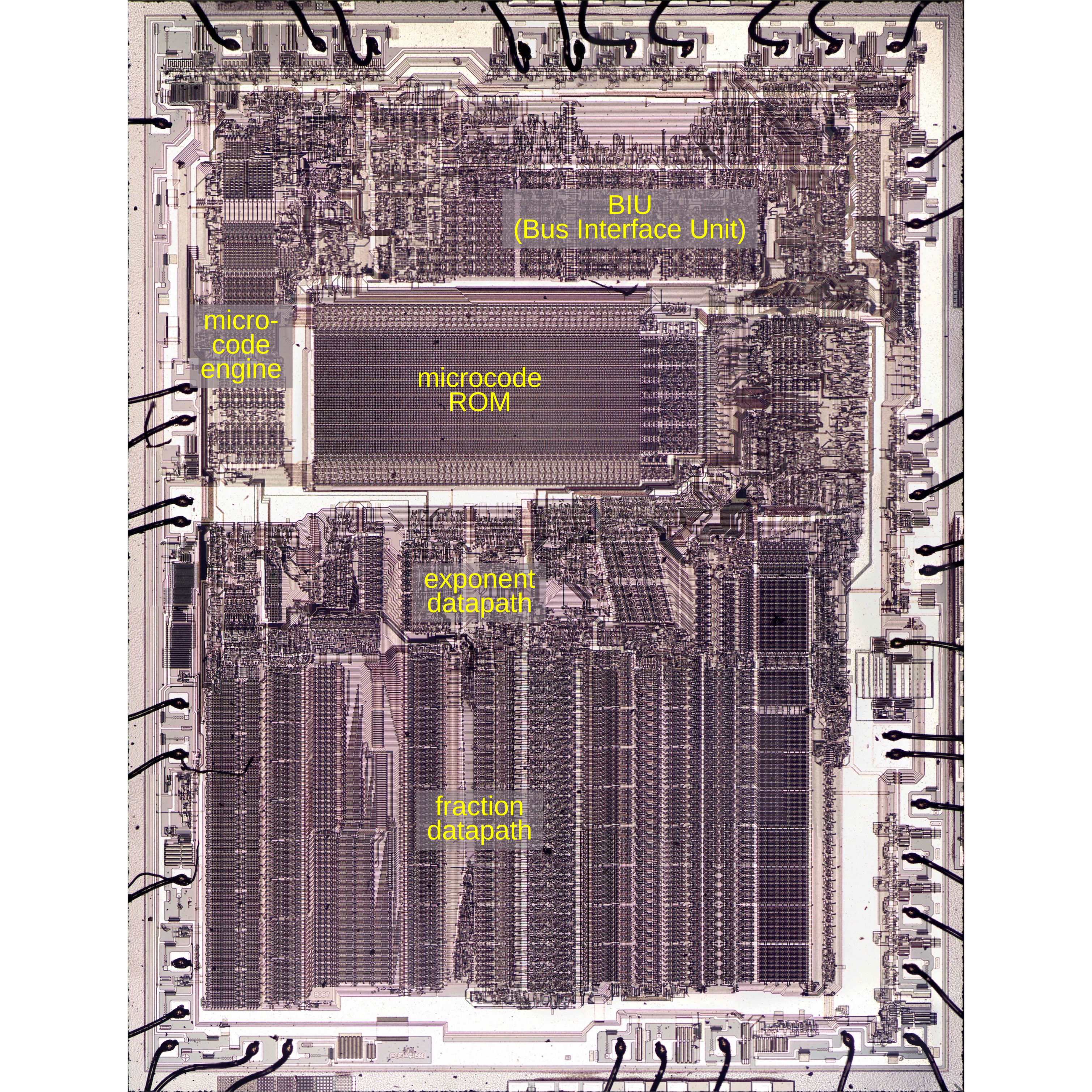
Die of the Intel 8087 floating-point unit chip, with main functional blocks labeled. The die is 5mm×6mm. Click for a larger image.
Zooming in on the bottom part of the chip shows the datapath circuitry; I've highlighted the relevant parts below.1 The exponent ROM holds various constants. The exponent converter is a specialized circuit that examines exponents, detects special values, and converts between exponent formats.2 The shifter is a large component; it allows a 64-bit3 value to be shifted left or right by arbitrary amounts. (I wrote about the 8087's shifter circuitry here.) The adder is the heart of the 8087's calculations; it is used in a loop for multiplication, division, and square roots. The B register holds one input to the adder, while multiple sources can provide the other input. The sum register holds the adder's output. The eight stack registers and the temporary registers hold floating-point numbers.
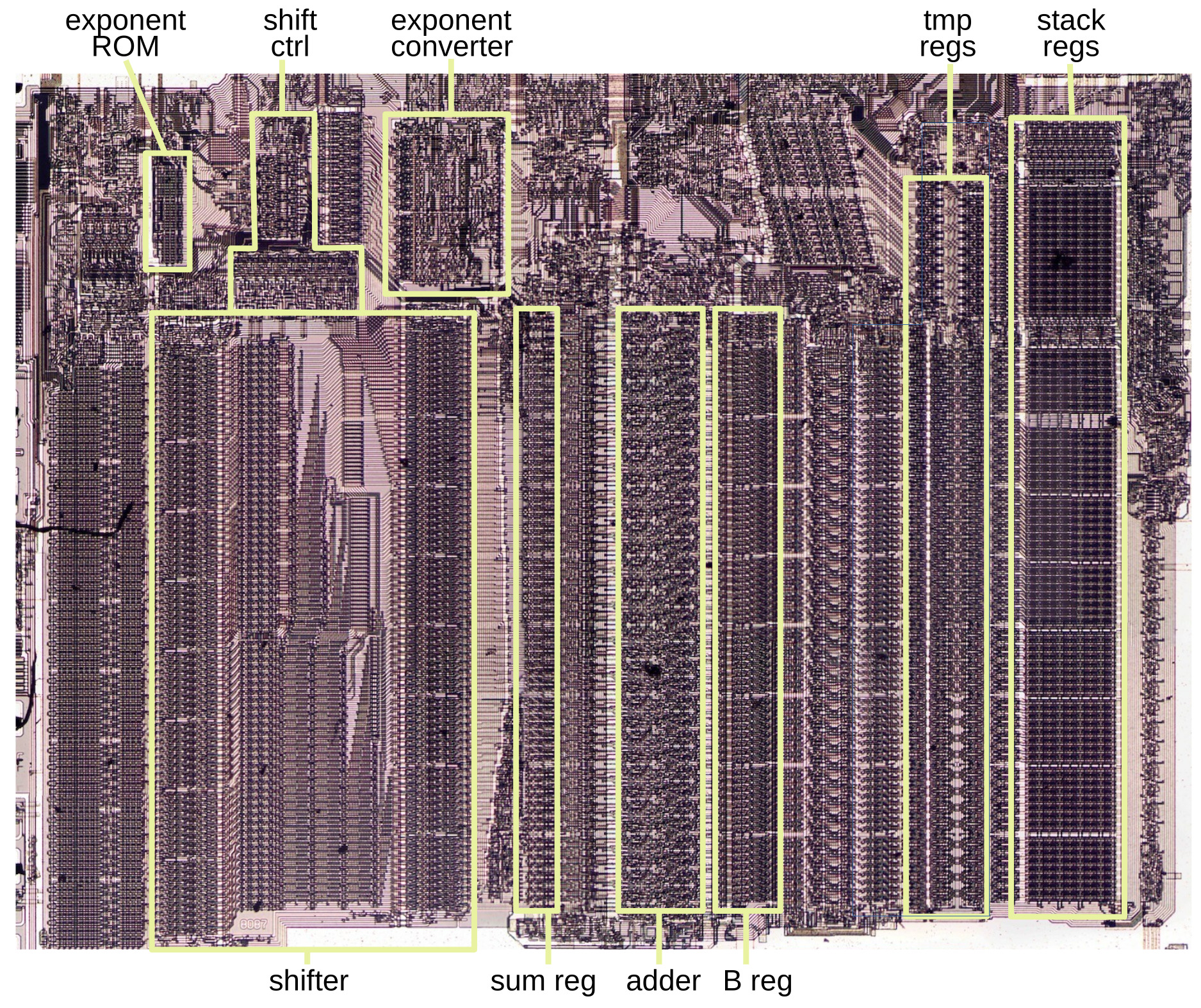
A close-up of the 8087's datapath, showing functional blocks that are used by FSCALE.
Details of the 8087
In this section, I'll explain some features of the 8087 that are important for the FSCALE microcode.
To use the 8087, a programmer stores values in its eight internal registers, organized as a stack. Each register holds an 80-bit floating-point number.
To optimize performance,
each value in the register stack has an associated "tag" value, which is mostly invisible to the programmer.
A tag labels a value as valid, special, zero, or empty.
A "normal" floating-point value is tagged as valid. If the floating-point value is infinity, Not a Number (NaN), or a denormalized value,
then it is tagged as special. A zero value is tagged as zero.
Finally, if a register is empty (e.g., its value has been popped off the stack), the register is tagged as empty.
The 8087 also has temporary registers that it uses internally: tmpA, tmpB, and tmpC.
Like the stack registers, tmpA and tmpB are 80-bit registers, along
with two tag bits. However, tmpC only holds a 64-bit significand.
The 8087 supports a variety of data types: floating-point numbers of various sizes, integers, and binary-coded decimal.
But internally, everything is stored as an 80-bit floating-point number called a "temporary real"; for the rest of this article,
I'll only be considering temporary real values.
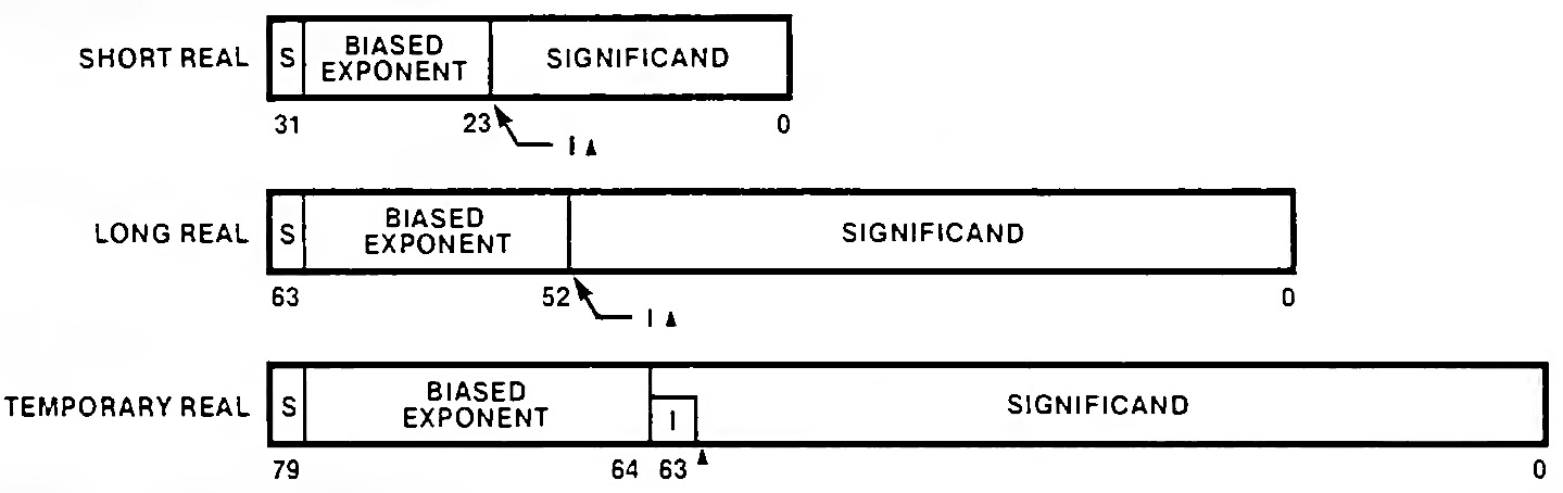
A number has three parts: the sign bit, the 15-bit exponent, and the 64-bit significand (the fractional part),
In most cases, a floating-point number is represented by sign × significand × 2exponent.
The significand is a 64-bit binary number of the form 1.bbb...:
a leading 1, followed by the binary point (the binary equivalent of the decimal point) and the rest of the bits.5
What makes floating-point numbers useful is that their scope covers the incredibly small to the astronomically large, thanks to the exponent, which
ranges from -16382 to 16383.
One important detail is that the exponent is stored with a "bias" of 16383 added to it. Thus, the stored exponent is always positive, even if the real
exponent is negative.6

The 80-bit temporary real format. The triangle indicates the binary point, analogous to the decimal point. From the Intel Numerics Supplement.
The 8087 supports several types of numbers that are represented as special cases with special exponents, as shown below. Zero and infinity have both positive and negative values. "Not a Number" (NaN) represents values that don't make sense, such as 0/0 or sqrt(-1); NaN has a large number of representations, not a single value. The 8087 also supports denormalized and unnormalized values, which are extremely small values where the significand doesn't have a leading 1.
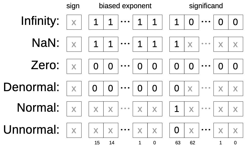
The encoding of special values. Based on Table S-31 in the Intel Numerics Supplement, but highly simplified. The "x" bits are arbitrary, as long as they don't conflict with another type.
The 8087 has a complicated exception system with six types of exceptions to indicate if something went wrong with an arithmetic operation. The most serious is the "invalid operation", indicating that the operation does not make sense, such as 0/0 or ∞-∞. It also includes accesses to an empty register (stack overflow or underflow) or operations on a NaN value. The 8087 also has an overflow exception if a value is too large to store, an underflow exception if a value is too small, and a divide-by-zero exception (excluding 0/0). A denormalized operand exception indicates that the result is too small to store as a normal value, but can be stored as a denormalized value. Finally, a precision exception indicates that a value cannot be represented exactly and must be rounded. (Precision exceptions are very common; even 1/10 will yield one.)
The 8087 provides fine-grain control over each exception type, specified by bits in the control register. If an exception is unmasked, the 8087 sends an interrupt to the 8086 processor, which handles the problem in software, for instance by terminating the program or logging an error. Alternatively, the exception can be masked and the 8087 will continue execution as best it can. For instance, an invalid result will be replaced by NaN, while an overflow or divide-by-zero will be replaced by infinity. A precision exception will result in rounding. The point of masked exceptions is that calculations continue, yielding an answer that is as accurate as possible; in most cases, this is what the programmer wants.
These features make the 8087 flexible and provide accuracy, but they also make the microcode much more complicated, since the combinations of special cases need to be handled appropriately.
The 8087's microcode
Executing an 8087 instruction can require hundreds of internal steps to compute the result. These steps are implemented in microcode with micro-instructions that specify each step of the algorithm. (Keep in mind the two levels of instructions: the assembly language instructions used by a programmer and the undocumented low-level micro-instructions inside the chip.) The microcode ROM holds the 1648 micro-instructions that implement the 8087's instruction set. I'm working with the Opcode Collective to reverse-engineer the micro-instructions and fully understand the microcode (link).
The 8087's micro-instructions are complicated, with many corner cases and ad hoc functions, but I'll provide a simplified overview. Each micro-instruction consists of 16 bits, as shown below. The first three bits specify the micro-instruction's type, which controls the meaning of the remaining bits. The first type is a transfer operation, which transfers data from one internal register to another. The two fields specify the source and destination. The three remaining bits are used for various special cases. Next is a shift operation, which uses the barrel shifter to shift a value left or right. The third type of micro-instruction controls the adder (which can also subtract). The miscellaneous instructions include stack pointer operations, tag modification, exceptions, and subroutine return. The far jump and far call micro-instructions perform a jump or subroutine call to a target micro-address in a fixed list. The condition field allows conditional jumps/calls/returns based on numerous conditions, while the last bit inverts the condition. A local jump is a relative jump to a nearby micro-instruction.
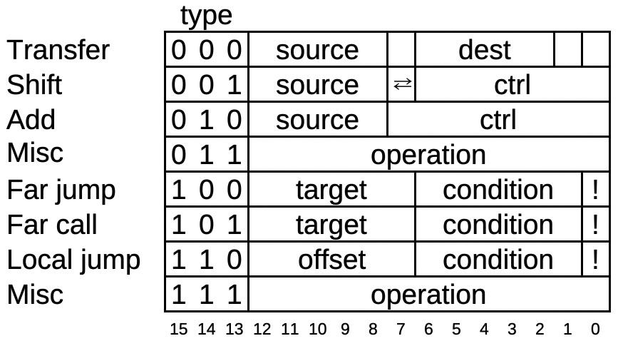
Structure of an 8087 micro-instruction.
The FSCALE microcode
When the 8087 starts executing an instruction, the instruction decoder circuitry determines the starting address of the microcode corresponding to the instruction.
This 11-bit address is loaded into the microcode engine, which starts executing the microcode.7
The microcode for FSCALE (shown below) starts at decimal address 748.8
The idea behind FSCALE is straightforward: if you want to scale a floating-point number by 2N (for an integer N),
you add N to the number's exponent.
This allows you to multiply or divide by a power of two much faster than using the full floating-point multiplication operation.
However, the microcode for FSCALE is unexpectedly complicated and uses several microcode subroutines.
In brief, the microcode first checks for arguments that are zero and then handles other special arguments.
It converts the scale argument to an integer and adds it to the exponent. Finally, it handles any overflow or underflow.
In more detail,
the microcode routine starts by moving the first argument from the top of the stack (st(0)) to the tmpA temporary register.
If the argument is zero, the routine immediately returns. (Thus, scaling 0 by anything—even NaN—will give a result of 0.)
Next, the second value on the stack (the second argument) is moved to the tmpB temporary register.
Likewise, the code returns if this value is 0, so scaling anything by 0 leaves the value unchanged.9
Next, a constant value is selected; selecting a constant and using it are two separate micro-instructions.
(The 8087 has separate ROMs for 16-bit exponent constants and 67-bit significand constants; this one is an exponent constant.)
In the normal case, execution jumps to address #0763, skipping the call to subroutine SPECIAL_TMPS.
FSCALE:
#0748 st(0) -> tmpA        Input argument from top of stack
#0749 jmp #0776 if tmpA:tag ZERO Bail if 0
#0750 stackPtr++
#0751 st(0) -> tmpB        Scale argument from stack(1)
#0752 stackPtr--
#0753 jmp #0776 if tmpB:tag ZERO Bail if 0
#0754 expconst 0x403e      Const 403e: exp shift to convert to int
#0755 jmp #0763 if not tmp empty/special/div
#0756 call SPECIAL_TMPS    Special handling
#0757 jmp #0762 if flag
#0758 jmp #0761 if not tmpB:tag SPECIAL
#0759 except:invalid       Invalid exception, use NaN
#0760 NaN -> tmpA
#0761 jmp #0776 if intr
#0762 jmp #0775 if expConv[0] Return tmpA if expConv set, otherwise continue
#0763 tmpB:exp -> Breg     Normal path
#0764 tmpB:sign,exp -> expConv ExpConv will test tmpB's sign
#0765 expConst -> tmpC     Const 403e
#0766 adder: tmpC - Breg cin=1 403e-exp is amount to shift to convert tmpB to int
#0767 sumreg:frac -> shiftcount Store in shifter control
#0768 shift tmpB:frac R count byte bit Perform the shift
#0769 shift R -> Breg      Breg holds scale argument as an int
#0770 jmp #0777 if neg     Negative Breg needs separate handling
#0771 adder: tmpA:exp + Breg cin=0 Add the scale to the exponent
#0772 sumreg:frac -> expConv Put result in expConv to check
#0773 sumreg:frac -> tmpA:exp Update exponent with sum
#0774 call NONNORMAL_RESULT if not exp normal Handle overflow/underflow
#0775 tmpA -> st(0)        Save result back to stack
#0776 RNI                  Done: Run Next Instruction
#0777 adder: tmpA:exp - Breg cin=1 Subtract Breg
#0778 jmp #0772            Continue processing
Continuing at #0763, the second argument is converted from a float to an integer, which takes a few steps.
For example, suppose the argument is 9, which in floating point is 1.001×23.
The significand bits 1000 are "left justified", but for an integer, these bits need to be "right justified" by shifting them to the right.
In general, if the exponent is n, the significand is shifted right by 63-n bits.
But recall that the exponent is biased by 16383. Thus, the significand must be shifted right by 63-(exp-16383) bits, that is 0x403e-exp bits.
(This explains the constant 0x403e earlier in the microcode.)
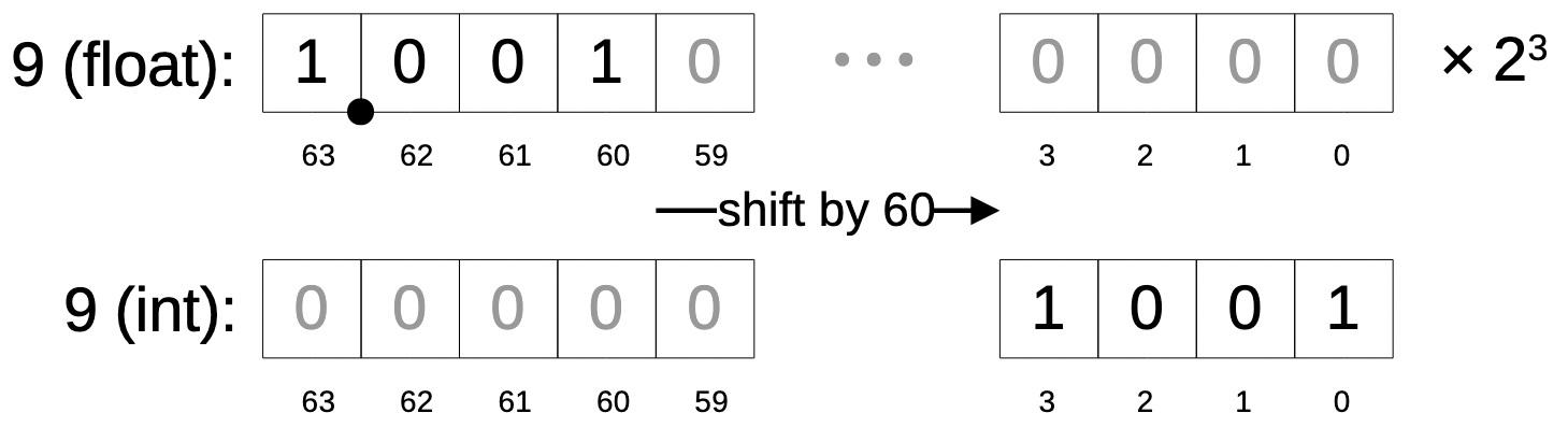
Converting a float to an int by shifting.
In the microcode, the subtraction takes several steps.
At #0763, the exponent of the second argument is moved to the B register, one of the inputs to the adder (completely different from tmpB).10
Next, the sign and exponent are moved to the exponent converter, a circuit that, among other things, tests for overflow.
Next, the constant 0x403e (selected back at #0754) is moved to the tmpC register.
At #0766, the adder is activated, subtracting the exponent from the constant.11
The adder puts the result into the sum register, and this value is copied to the shift count register, which controls the shifter.
This value indicates how many bits the second argument must be shifted to convert it to an integer.
At #0768, the shifter is activated to shift by the desired amount, using both the bit shift part and the byte shift part.
As with the adder, activating the shifter and reading the result are separate micro-instructions; the result is put into the B register.
The core part of the FSCALE instruction is finally performed at #0771, adding the second argument to the first argument's exponent.
The adder is activated to add the B register value (the scale) to the exponent, and the updated value is stored in tmpA's exponent.
(Except if the scale factor is negative, it is subtracted via the #0777 path.)12
The value is also sent to the exponent converter circuit, which checks the exponent for overflow or underflow; if so, subroutine NONNORMAL_RESULT is called.
But in the normal case, the updated value is copied from tmpA to the top-of-stack register st(0).
Finally, RNI (Run Next Instruction) indicates that the microcode routine is done and the instruction is completed.
Thus, even in the straightforward case, FSCALE takes about 22 micro-instructions.
Handling empty or special arguments
What happens if an argument accesses an empty stack location (i.e. stack underflow) or is a special value (infinity, denorm, NaN)?
These cases are handled by a micro-subroutine that I'll call SPECIAL_TMPS15 because it processes special values in tmpA and/or tmpB.
This subroutine is a general-purpose routine, used by basic arithmetic operations, FSCALE, FTST (test), and FPREM (partial remainder).
The control flow through SPECIAL_TMPS is rather convoluted since the code must prioritize issues if,
say, one argument is empty and the other is a denorm.
I'll just give a brief summary; see the footnote13 for details.
First, the subroutine converts any denorms to unnorms. Then it checks for access to empty stack locations, raising an exception or interrupt if so.
Then it checks the two arguments again. If either is NaN, an exception or interrupt is triggered. Otherwise, it returns a status indicating the type of arguments.
Unexpectedly, if both arguments are NaN, the code compares the two NaN values and returns the larger.
This behavior may seem very weird, but it's a documented feature.14
You might think that NaN is a single value, but it's actually an enormous family of values.
The idea was that the programmer could use different NaN values to signal where a problem occurs. For instance, you could put a different
NaN in each location of an uninitialized array, so you could tell which position was accessed.
For some reason, the designers of the 8087 decided that if you perform an operation with two different NaNs, the result is the larger one.
Thus, the microcode needs code that detects if both operands are NaN and computes the larger, using a subtraction for the comparison (#1518).
SPECIAL_TMPS (J5):
#1484 call SPECIAL_VAL if tmpA:tag SPECIAL Handle special values in tmpA/tmpB
#1485 xchg tmp
#1486 call SPECIAL_VAL if tmpA:tag SPECIAL Handle tmpB special
#1487 xchg tmp
#1488 1 -> flag            Flag=1 by default
#1489 jmp #1500 if not tmp empty/special/div 0 -> expConv if tmps okay
#1490 1 -> expConv
#1491 jmp #1497 if not tmpA/B empty
#1492 except:invalid       Invalid if either empty
#1493 jmp #1525 if compare instruction No NaN for comparison
#1494 jmp #1511 if intr    Return if interrupt not masked
#1495 NaN -> tmpA          NaN if interrupt masked
#1496 return
#1497 jmp #1502 if tmpA:tag SPECIAL Special cases
#1498 jmp #1505 if tmpB:tag SPECIAL
#1499 0 -> flag            Div normal path:
#1500 zero -> expConv      Return flag 0, expConv 0
#1501 return
#1502 call SPECIAL_VAL     TmpA special
#1503 jmp #1512 if not flag Jump if NaN, fallthrough if infinity
#1504 jmp #1509 if not tmpB:tag SPECIAL
#1505 xchg tmp             TmpB special
#1506 call SPECIAL_VAL
#1507 xchg tmp
#1508 jmp #1521 if not flag Jump if NaN, return if infinity
#1509 0 -> flag            Clear flag, return
#1510 return
#1511 RNI                  End instruction with interrupt
#1512 jmp #1522 if not tmpB:tag SPECIAL TmpA NaN, now check tmpB
#1513 xchg tmp
#1514 call SPECIAL_VAL     Check tmpB
#1515 xchg tmp
#1516 jmp #1522 if flag    Jump if tmpB is not NaN
#1517 except:invalid       Invalid exception
#1518 tmpB:frac -> Breg    Both args are NaN, find larger
#1519 adder: tmpA:frac - Breg cin=1
#1520 jmp #1522 if adder sign See if tmpA < tmpB
#1521 tmpB -> tmpA         Take larger
#1522 except:invalid       Invalid exception
#1523 jmp #1525 if compare instruction No interrupt for comparison instruction
#1524 jmp #1511 if intr    End instruction with interrupt
#1525 1 -> flag            Return with flag set
#1526 return               End of J5
This subroutine makes heavy use of a helper subroutine, SPECIAL_VAL,16 that processes one argument.
The helper converts a denormalized argument to an unnormalized argument, raising an exception or interrupt as appropriate. It also flags an input of infinity.
The hardware for the micro-instruction that exchanges tmpA and tmpB at #1485 is interesting.
Instead of physically moving the values between the two registers, the micro-instruction toggles a flip-flop that exchanges the meaning of tmpA and tmpB.
That is, if the flip-flop is set, a reference to tmpA goes to tmpB and vice versa.
(This is a standard trick in microprocessors; the Intel 8080's XCHG instruction exchanges the DE and HL registers in a similar way.
The Z80 uses the same trick for the EX and EXX instructions to exchange the regular register set with the secondary register set.)
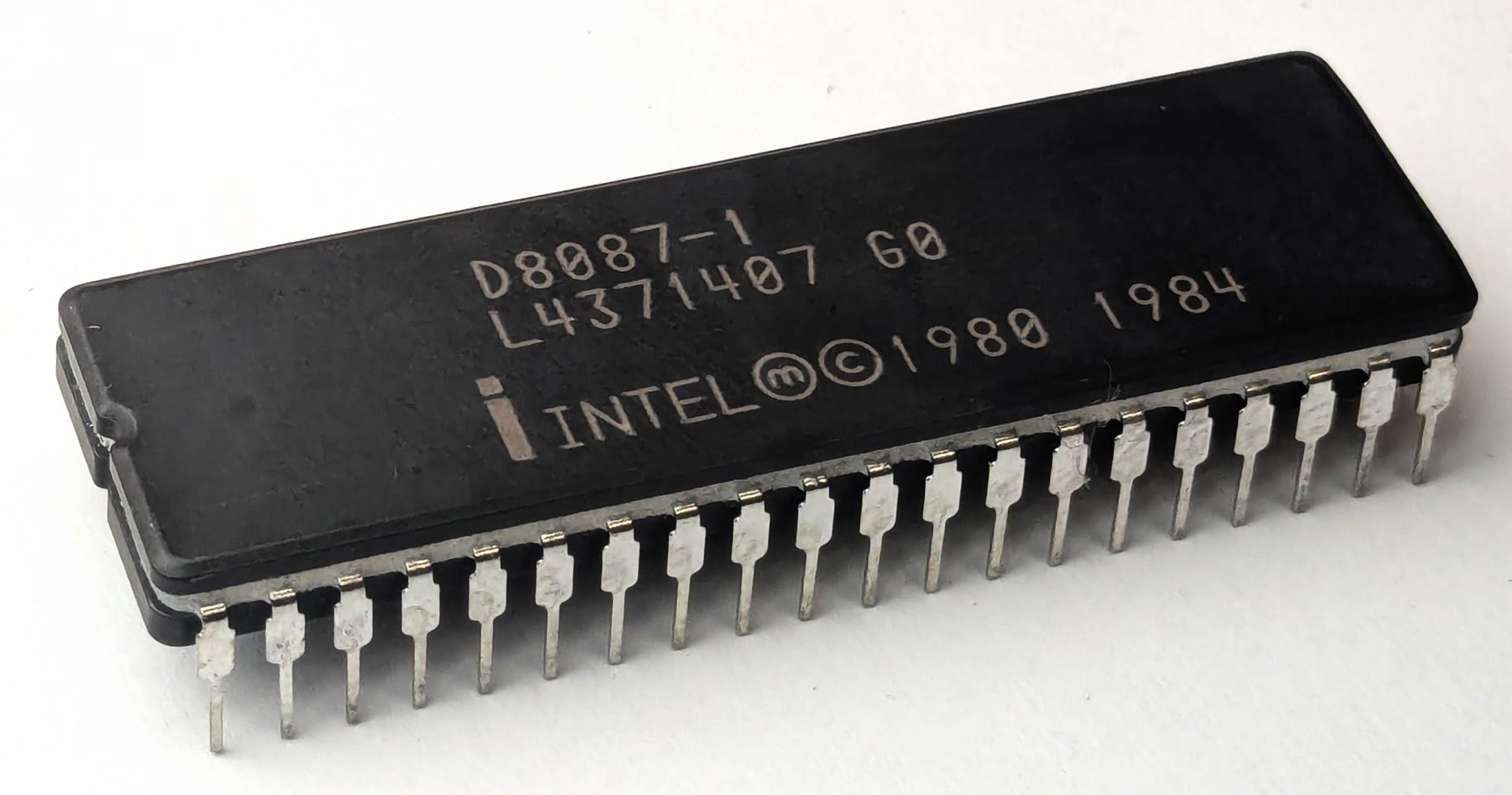
The Intel 8087 chip is packaged in a 40-pin DIP (dual in-line package), as are the 8080 and Z80. This photo is here as a break from all the microcode.
Handling a non-normal result
If you take a very large number and scale it larger, you can end up with overflow. If you take a very small number
and scale it smaller, you can end up with a denormalized number or underflow.
This will trigger an overflow, denorm, or underflow excaption, and an interrupt if unmasked.
Moreover, the 8087 supports four rounding modes:
round to nearest valid value, round down (toward -∞), round up (toward +∞), or round (chop) toward zero.
Depending on the rounding mode, an overflow can result in either ∞ or the largest possible floating-point number.
Similarly, an underflow can result in either zero or the smallest possible floating-point number.
And depending on the infinity mode (affine or projective), infinity can be either signed or unsigned.
Thus, the FSCALE microcode needs to handle many special cases for the result.
The subroutine to handle a non-normal result in tmpA is below.
One interesting micro-instruction is update overflow/underflow exceptions, which triggers an exception if appropriate.
For most exceptions, a micro-instruction triggers the exception (for example, except:precision at #0346).
But for the overflow and underflow exceptions, the microcode delegates the task to hardware.
Specifically, the 8087's "exponent converter" circuit examines the exponent to see if an overflow
or underflow exists, based on the selected floating-point precision.
The micro-instruction sets the overflow and underflow flags based on these values.
Thus, a complex task is performed by a single microcode instruction, thanks to the hardware support of the exponent converter.
NONNORMAL_RESULT (J16):
#0318 return if tmpA:tag ZERO Handle non-normal result
#0319 update overflow/underflow exceptions Trigger exceptions if exp conv says to
#0320 expconst 0x6000      The interrupt bias constant 0x6000
#0321 jmp #0329 if not intr
#0322 expConst -> Breg     Interrupt path
#0323 jmp #0326 if neg
#0324 adder: tmpA:exp + Breg cin=0 Add bias for underflow
#0325 jmp #0327
#0326 adder: tmpA:exp - Breg cin=1 Subtract for bias overflow
#0327 sumreg:frac -> tmpA:exp New exponent to tmpA
#0328 return               Interrupt, so done
#0329 jmp #0344 if neg     Masked exception
#0330 tmpA:exp -> Breg     Underflow
#0331 adder: 1 - Breg cin=1 Amount to shift denormal
#0332 call CREATE_DENORM   Create a denormal
#0333 adder: zero + Breg cin=0, roundmode Add zero to round
#0334 call ADJUST_PRECISION Adjust to specified precision
#0335 jmp #0340 if Sum register is zero If zero, return +/- zero as appropriate
#0336 zero -> tmpA:exp     Denorm: exponent is 0
#0337 sumreg:frac -> tmpA:frac Save denorm fraction
#0338 special -> tmpA tag  Tag denom as special
#0339 return
#0340 tmpA sign -> sign latch Return +/- zero
#0341 zero -> tmpA
#0342 sign latch -> tmpA sign
#0343 return
#0344 NaN/Inf -> tmpA:exp  Overflow: maybe return infinity
#0345 tmpA:frac -> tmpB:frac Save tmpA frac in tmpB
#0346 except:precision     Set precision exception
#0347 Inf -> tmpA:frac     Put infinity in frac
#0348 special -> tmpA tag  Mark infinity as special
#0349 return if not round chop If rounding up, return infinity
#0350 1 -> Breg            Return max float: adjust down
#0351 adder: tmpA:exp - Breg cin=1
#0352 sumreg:frac -> tmpA:exp Exp=7fff-1=7ffe
#0353 adder: zero - Breg cin=1
#0354 sumreg:frac -> tmpA:frac Frac 0-1 = ff...ff
#0355 norm -> tmpA tag     Normal value
#0356 return if tmpB:frac[63] Return max float unless unnorm
#0357 tmpB:frac -> tmpA:frac Return original tmpA frac
#0358 return
The 8087 has interesting behavior if an overflow or underflow is unmasked and an interrupt occurs.
The idea is to let the interrupt handler know what the exponent should have been.
However, the proper value can't be used since it is too big or too small to fit in the exponent field (which is why the exception occurred).
The solution is to add or subtract the constant 0x6000, resulting in an exponent that fits.
The interrupt handler can subtract or add this constant to get the correct exponent.
Lines #0322 to 0328 perform this addition or subtraction.
For a masked underflow, a denorm value is created by the subroutine CREATE_DENORM.
The value is rounded to the specified precision by ADJUST_PRECISION.
Finally, if the value is too small for a denorm, the value +0 or -0 is returned as appropriate.
For a masked overflow, the 8087 either returns Infinity or the largest-possible float, depending on the specified rounding mode.
Infinity is represented by an exponent of all 1s, and a significand of 1000...; these values are loaded directly onto the bus by transistors.
The maximum float, however, is computed: 1 is subtracted from the infinity exponent, and 1 is subtracted from a zero significand.
Helper subroutine: creating a denormal
One controversial feature of the 8087 is denormals, numbers that are smaller than "regular" floats. Recall that floating-point numbers have a significand with the first bit set to 1. But what happens if you hit the smallest possible exponent and want an even smaller number? The 8087 lets you break the rule that the significand starts with 1, producing smaller numbers known as denormalized numbers or denorms. Denorms significantly extend the range, providing numbers up to a factor of 263 smaller. However, denorms don't have as much precision since the upper bits are "wasted". Moreover, calculations with denorms can be substantially slower because special handling is required.
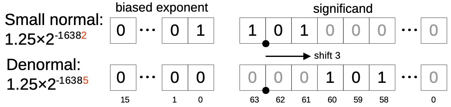
Example of a normal number, reduced by a factor of 8, resulting in a denormal.
The diagram above shows a normal number with the minimum possible exponent (-16382, which is 1 after biasing). Dividing the number by 8 (or scaling by -3) creates a denorm since the exponent can't be reduced any further. Instead, the significand is shifted 3 bits to the right. The exponent is replaced with the special value 0, indicating that the number is a denorm.
In the 8087, denorms are created by a microcode subroutine that I'll call CREATE_DENORM;
it is used by many arithmetic operations, not just FSCALE.
This subroutine takes a normal number and a shift amount. By shifting the normal number (as in the example above), it creates a denormalized number.
The microcode (below) uses the exponent converter to check if the shift is 64 or more.
If so, there will be nothing left after the shift, so zero is returned.
Otherwise, the value is shifted to the right and the denorm is stored in the B register.
CREATE_DENORM (J20):
#0522 sumreg:frac -> expConv Create denorm
#0523 sumreg:frac -> shiftcount Number of bits to shift
#0524 jmp #0528 if exponent[6:14] == 0 Jump if < 64
#0525 zero -> Breg         No bits left, use zero
#0526 shift tmpA:frac L 0 bytes, 0 bits Run through shifter?
#0527 jmp #0532
#0528 shift tmpA:frac R count byte bit Shift right by the specified amount
#0529 shift R -> Breg      Result to Breg
#0530 shift tmpA:frac L ~count byte bit Now shift back for sticky test
#0531 NOP                  Wait for shifter
#0532 rounding(h) -> Breg[grs] Store the three rounding bits in the Breg
#0533 return
But why is the value then shifted to the left (#0530)?
The purpose of this is to get the rounding bits.
One of the principles of the 8087 is to get rounding correct, which is a lot harder than it seems.
In order to decide how to round up a number, you need to keep track of an impossibly large number of bits.
For instance, if you calculate 1 + 0 and round up, you get 1.
But if you calculate, say, 1 + 2-10000 and round up, you get a float a bit higher than 1.
The problem is how do you distinguish the two sums before rounding, without storing thousands of bits?
The trick is that the 8087 keeps three bits for use in rounding: the "guard" bit, the "round" bit, and the "sticky" bit. If you consider a "tail" of bits to the right of the significand, the guard bit is the most significant bit of the tail, followed by the round bit. The sticky bit is special: it is the OR of all the remaining bits in the tail, indicating if any of them are 1. Thus, 1 + 2-10000 has the sticky bit set, while 1 + 0 does not, so the two values can be rounded up differently. To generate the sticky bit, the 8087 uses a very large 64-bit NOR gate that tests the tail bits in parallel.
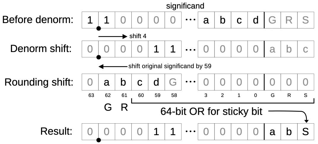
A diagram showing how the guard, round, and sticky bits are computed from a right shift. The numbers in this example are different from the previous example.
When a number is shifted to the right (e.g., when creating a denormal), bits are lost off the right.
To generate the rounding bits,
the value is shifted to the left, keeping all the tail bits that will eventually be discarded, and discarding the bits that will be in the final significand.
The top two bits go into the guard and round bits, while the remaining bits are ORed together to generate the sticky bit from the rest.17
The diagram above is an example of this process. Suppose the value is being shifted to the right by 4 bits. The tail bits abcd (or at least d) will get lost in the shift.
The rounding bits are computed by shifting the original significand to the right by 59 bits (the complement of 4). Bit 62 (a) becomes the new guard bit,
bit 61 (b) becomes the new round bit, and the OR of the remaining 64 bits becomes the new sticky bit. (Note that the old guard, round, and sticky bits get
ORed in too, so they aren't lost.)
Merging the significand from the first shift with the rounding bits from the second shift produces the desired result.
Helper subroutine: adjusting precision
Although the 8087 supports three lengths of floats, it performs all calculations with 80-bit "temporary reals".
At the end of an instruction, it converts the result to the desired length. (As a consequence, most instructions aren't any faster if you use a shorter float.)
A microcode subroutine, which I call ADJUST_PRECISION, converts the result to the precision that is specified in the 8087's control word,
using the specified rounding mode.
This subroutine is used by most of the arithmetic instructions.
The first code path handles temporary reals (which have 64 bits of precision). The control word specifies one of four rounding modes. However, there are only two actions that can be taken for a particular significand: either round down (chop) or round up (chop and increment by 1). This decision is made by complicated logic circuits that examine the rounding bits, the rounding mode, and the sign to determine whether to round up or down. This simplifies the microcode but makes the hardware more complicated. The microcode performs a conditional return, returning if the significand doesn't need to be rounded up. Otherwise, the microcode increments the significand by adding 0 with a carry-in. It then checks for overflow, in which case it replaces the value with Infinity and sets a special flag.18
ADJUST_PRECISION (J11):
#0299 jmp #0306 if not precision64
#0300 return if not round up, update CC1 Update condition code, maybe return
#0301 adder: sumreg:frac + 0 cin=1 Add 1 to round up
#0302 return if not sumreg[64]
#0303 Inf -> sumreg:frac,sign Return infinity if overflow
#0304 2count++             Set special flag
#0305 return
#0306 23/52 -> shiftcount  Short or long real: get appropriate shift
#0307 shift sumreg:frac,rnd L count byte bit sticky Shift to generate rounding bits
#0308 NOP                  Wait for shifter to complete
#0309 rounding(H) -> sumreg[grs] Store rounding bits
#0310 shift sumreg:frac R ~count byte bit Shift right to drop excess bits
#0311 shift R -> sumreg:frac
#0312 jmp #0314 if not round up, update CC1 Update condition code
#0313 adder: sumreg:frac + 0 cin=1 Round up if appropriate
#0314 shift sumreg:frac L ~count byte bit Shift left to realign
#0315 shift L -> sumreg:frac,sign
#0316 return if not sumreg[64] Return if not overflow
#0317 jmp #0303            Return infinity
The code is more complicated when
returning a smaller precision (short real or long real), since the significand must be shortened.
First, the code at #0306 loads the shifter with either 23 or 52, depending on the precision specified in the control word, and then shifts the
value left. This produces the rounding bits as in the previous section.
Next, the value is shifted to the right, shortening it to the desired length.
As before, the significand is incremented or not, depending on whether it should be rounded up or not.
Finally, the value is shifted back to the left, so the most significant bit of the significand is on the left.
As before, if rounding up caused an overflow, infinity is returned.
One bizarre feature is that a jump with the "round up" conditional also has a side effect of updating the 8087's programmer-visible condition code register (CC1), indicating
if the result was rounded up or down.
That is, the 8087 has extra circuitry to detect this specific condition and load the value into the condition code latch.
Strangely, the 8087 documentation doesn't describe this condition code action; Intel didn't document it until the 387SX floating-point chip in 1987.19
Conclusions
Floating-point has a long history before the 8087. For instance, the IBM System/360 mainframes (1964) supported 32-bit and 64-bit floating-point numbers. In 1977, AMD introduced the Am9511 floating-point chip, supporting 16- and 32-bit floating-point numbers, along with transcendental functions. What made the 8087 revolutionary is that it was carefully designed to be as mathematically accurate as possible, largely thanks to numerical expert William Kahan. (The 8087 led to the IEEE 754 Standard, now used by almost every computer and ending the anarchy of incompatible floating-point standards.)
The 8087 ended up extraordinarily complicated with three different sizes of floating-point numbers, four sizes of integers, four rounding modes, infinity modes, a collection of exceptions that could be masked or unmasked, denormalized and unnormalized numbers, signed and unsigned infinities, signed zeros, and a whole family of Not-a-Numbers. These features combine, yielding many corner cases. The 8087 deals with this complexity both through specialized circuits and through tangled microcode.
How complicated is the 8087? For users who didn't have an 8087 chip, Intel sold an 8087 Support Library that exactly emulated the 8087's instructions (but much slower). The emulator took 16K bytes of 8086 code, which was a lot when a full BASIC interpreter could fit in 8K. Another way of looking at this is that the hardware of the 8087 drastically reduced the amount of software required: the 8087 itself used 3.3K of microcode, compared to the 16K for the emulator in 8086 code.
I plan to continue reverse-engineering the 8087 microcode; for updates, follow me on Bluesky (@righto.com), Mastodon (@[email protected]), or RSS. I've been working on this with the members of the "Opcode Collective", especially Smartest Blob and Gloriouscow, who converted the ROM images to microcode data and extensively analyzed the contents. See the 8087 repository on GitHub for more.