This year I went to my first DEF CON (I know, I'm overdue). I had a blast - saw lots of old friends, made lots of new ones, and generally just had a good time. I'm on the more introverted side though, and I wanted to give others a reason to talk to me. I decided to build a custom choker.
I knew roughly what I wanted my choker to look like. There needed to be a screen in the center and LED strips on the side. It should look sleek - the bezels should be small, the device itself should be thin, and it should be relatively self-contained. It should be attractive to look at.
The attractiveness is worth noting because it's not something I usually optimize for when starting a project. Sure, I don't want my devices to be ugly, and they ideally should look semi-professional, but beyond that I'm not too picky. Making something that looked good would be a fun - and different! - challenge.
I figured I would start by selecting a screen.
Selecting a screen
I use screens a lot in my projects, but they're generally just a functional part. As a result I usually use whatever is cheapest wihile serving my purposes. In this case, I wanted something that looked nice. A cheap TFT panel or monochromatic OLED wouldn't do - I wanted a screen that looked nice. I also wanted to minimize the bezels.
One of my friends recommended that I check out Panelook. I hadn't heard of it before, but it's a giant marketplace for finding every niche screen you could possibly imagine. It's a bit of a strange website - you have to pay for datasheets - so once I narrowed down a screen I bypassed them and went directly to the manufacturer.
I ended up going with the Hello Lighting HL020E21-02. It's the perfect size, square with rounded corners, and has super small bezels. The image quality is good on paper too - AMOLED and 480x480. It's also a touch screen: not something I needed, but nice to have.
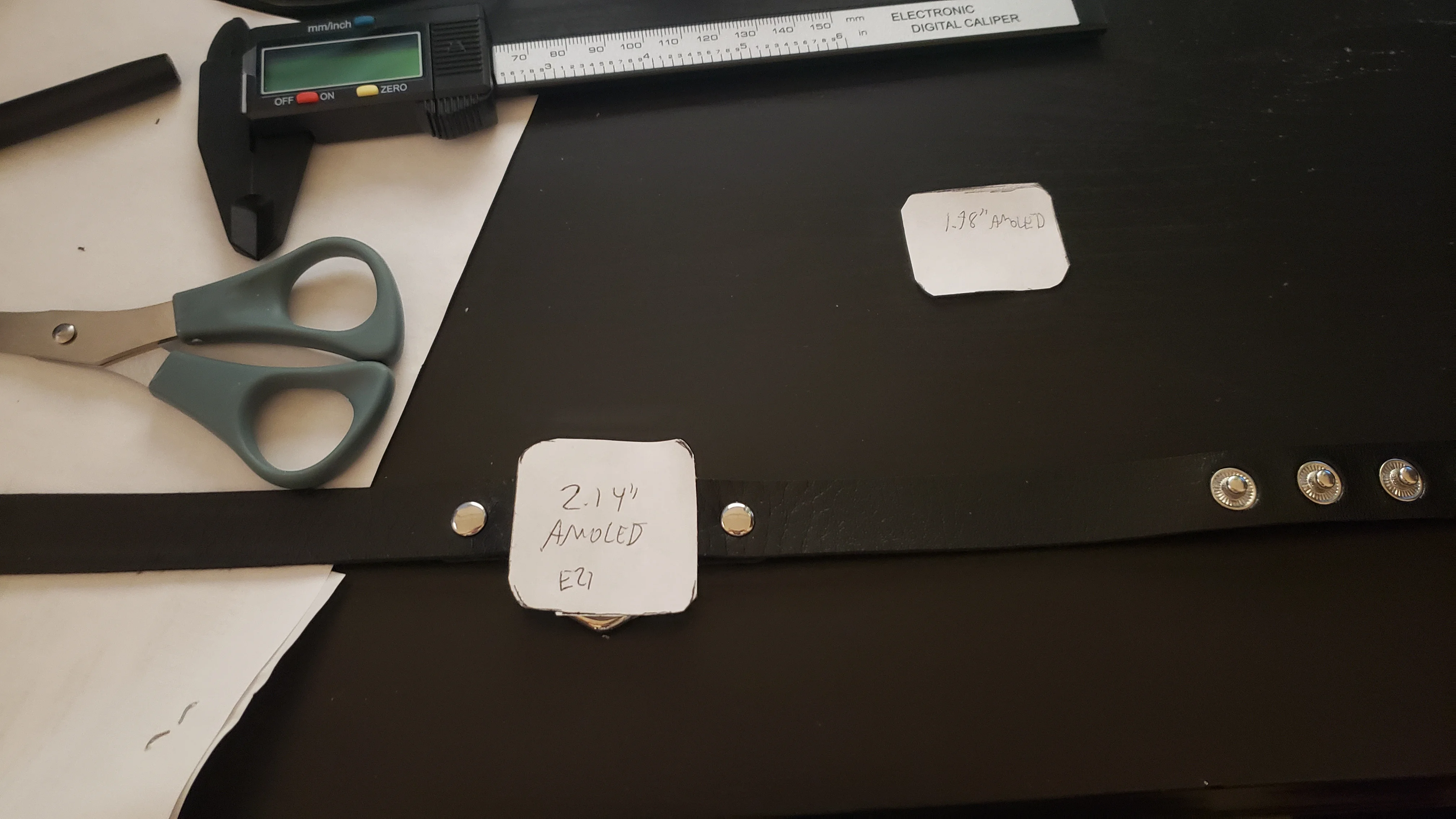
Believe it or not, for this super nice screen they only quoted me $12/unit! The catch was that it came with basically no documentation. I found this a bit daunting but decided to proceed with the order. Shipping was the dominant cost, so I bought 5 of them. I also bought 5 of the Hello Lighting HL017T03-01 just in case I wanted something a little smaller.
The displays took a few weeks to arrive from China. Doing some test fits made me quickly realize how happy I was with them. I hadn't internalized this properly before they arrived, but they were thin! Well under a millimeter thick for the actual glass, and about 2.3 mm thick where the display connector was.
Designing a board
With a display chosen, the board design was significantly more constrained - and that's a good thing. At a minimum, I needed it to fit behind the screen and have the correct peripheral to drive the display. It also needed to regulate battery voltage (including charging the battery).
I settled on the RP2350 for my microcontroller of choice. The PIO would allow me to drive the display, and it has more RAM than the RP2040. It would still be tight; with 16-bit colour, a single framebuffer is 450KiB.
Given that I had no idea what I actually wanted the choker to do, I figured it would be smart to also add a micro SD card. I put very little thought into this; I found some schematics for connecting the RP2350 to the SD card and copied them. I'd figure out the software later. As I'll discuss, I should have put a little more effort in here.
Honestly, the bulk of the board design effort was just figuring out the display. There was no existing KiCad footprint for it (or for any other EDA that I could find). The specifications of its connector, a 31-pin FPC, were also underspecified. Rather than list the dimensions of the connector, they gave an obscure model number of a compatible FPC. This returned almost no results and made it very painful to design a footprint.
Later I managed to track down an equivalent FPC that was much more popular and well-documented. I didn't discover this until after I ordered my board.
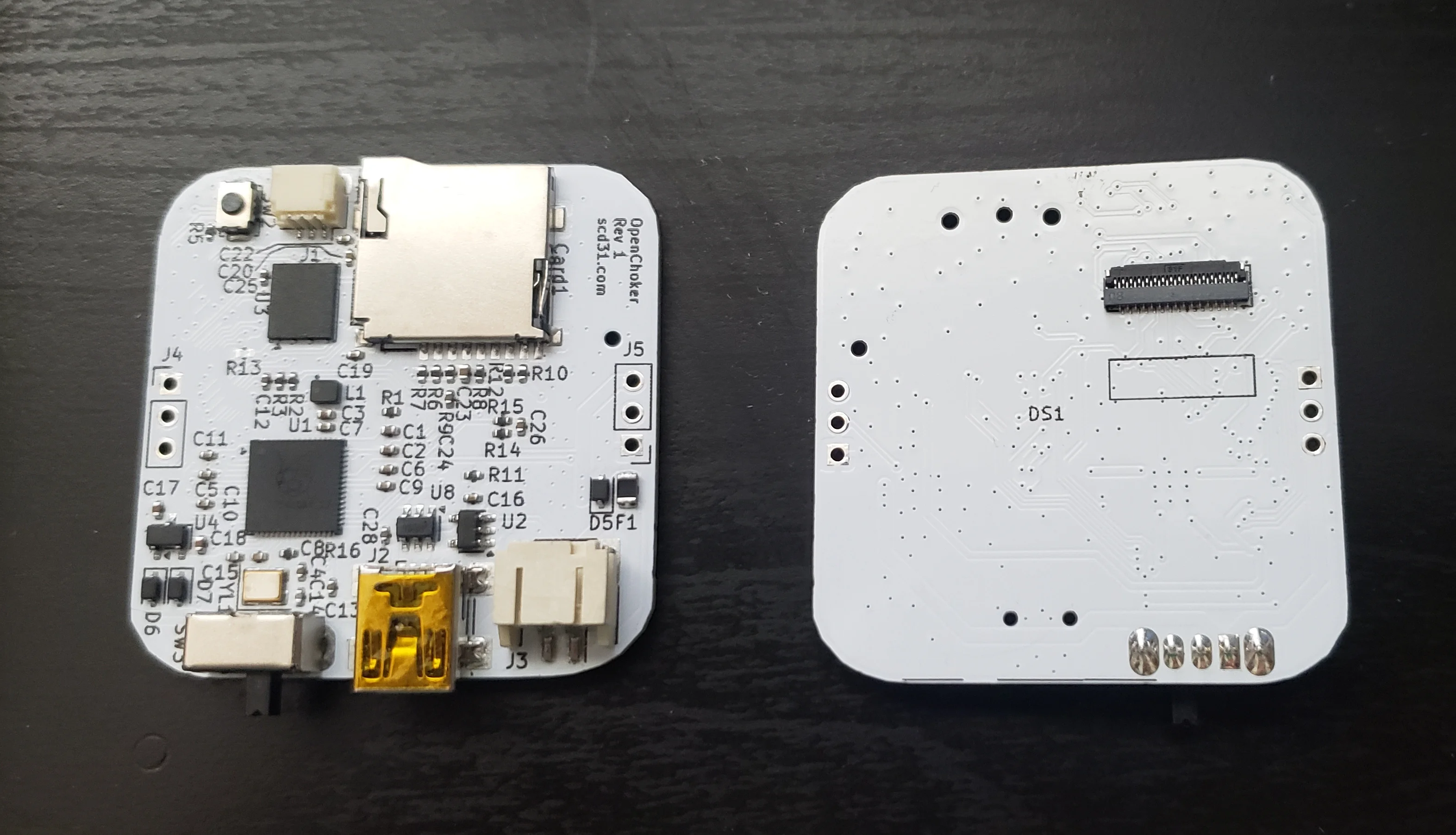
The design I ended up with was pretty simple - certainly much simpler than some of my other projects. One challenge was getting everything to fit - the components didn't take up much space, but the traces sure did! I went with a dual layer board, purely for the challenge. Four layers really aren't that expensive these days.
This board was designed to be just a little smaller than the screen. It would hide behind it, flanked by the lithium battery I would mount at the back.
After ordering the board, I decided the case was the next thing I'd work on.
The Case
To recap, I wanted the smallest, thinnest case, with basically no additional bezels. This is a far cry from what I'm used to designing!
I got quite good at FreeCAD during this project. It was absolutely miserable to use a few years ago, but recent versions are much better (certainly not perfect). Helpfully, my friend taught me some more advanced techniques, like VarSets. This made the project much more bearable.
I also went down quite a rabbit hole laser cutting a perfect acrylic piece to go in front of the screen. This would add some extra width but with the display being so thin, I was positive that there was meant to be some kind of protection there. It was after a solid week of working on this that I remembered it was a touch screen. Obviously they did not want me to put something in front of it!
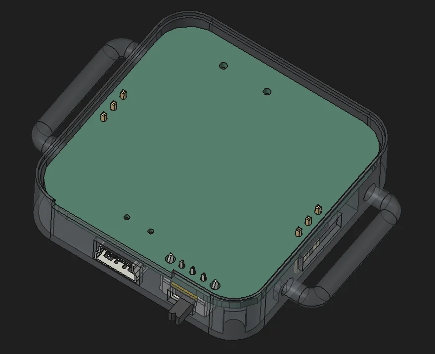
This is the case design I landed on. The screen rests on a tiny ledge, that is barely visible but provides very good structural support. The board sits directly below that. There are handles where the leather attaches, and square holes to run wires to the LED strips. Of course, there are holes for all of the connectors as well, such as the mini USB (my beloved), the debug connector, the micro SD card, and the power switch.
I decided to relocate the battery. When considering thickness, I forgot to account for the actual components on the board. This meant the device would be thicker than I wanted, and a test fit caused it to press on my neck just a bit too much to be comfortable. The weight was also front-loaded, and the battery capacity was quite small. I wanted my choker to last all day.
I went with an 18650 strapped to the back of the choker. This was not exactly safe - the protection circuitry lived in the case, so it was affixed with long, unprotected wires - but I figure I have done worse than walk around with a small bomb on my neck.
With the case done, I moved onto the software.
The Software
Something I think about a lot is that video is one of the last things that takes a relatively large amount of compute. Serving a website? That's pretty easy, it's just slinging some bytes around. My M68k can probably do it. Even audio streaming uses relatively little compute per stream.
But video is different. There are lots of uncompressed audio formats. Uncompressed video is much rarer - it just takes up so much space and uses so much bandwidth! For all practical purposes, we compress our videos. But now you need enough compute to decompress the video in real-time!
With a 480x480 display, I was now in the realm where performance mattered. As mentioned, a single frame at 16 bpp is 450 KiB. This meant I didn't even have enough room in RAM for double buffering. At 60 FPS, I was looking at transferring over 26 MiB/s of data (or over 210 Mib/s). That's not much less than the RP2350's flash bus can support!
I quickly realized that the single SPI lane of the SD card I wired up wasn't going to be useful - it could only manage about 3 MiB/s. That's not the end of the world; I can just generate a video on the fly.
Like I always do, I used embedded Rust for this project. I talk about this a lot, so all I'm going to say is it's simply delightful. I used Embassy, which is a framework I'm kind of new to, but I'm loving it.
It took me a good couple of days to get the screen to actually display anything. One complication is that the screen's bus is write-only. This makes it very difficult to pinpoint where a problem is. I eventually got it working with a single-lane SPI driver, and then wrote a PIO program so that I could drive it at maximum speed on the quad bus.
The touch controller took a bit of debugging as well; it was documented even worse than the display controller. Luckily I could at least debug pieces of it individually.
Here's the animation I ended up with:
It's pretty simple. Even so, when drawing all four images on a colour-changing background, the framerate dips to 30 FPS on the hardware. This is a combination of high bus usage and high CPU usage. If I could fit two frames in RAM at a time, it would be trivial to improve the performance. The 30 FPS dips weren't noticeable though, so I decided not to worry about it too much.
I decided to allow people to draw on the screen by dragging their finger on it. Aside from this, the touch screen could also be used to enter a menu for controlling the LED strip and display brightness.
The Leather
I went down quite a rabbit hole trying to find leather. There are like, a million types of leather. Some are stretchy, some are soft, some can be laser-cut, but lots can't. I researched this on-and-off for a good few weeks trying to decide on what I wanted. One of my friends, who's into leatherworking, mentioned it may even be worth using two different types of leather - a soft leather on the inside for comfort, an something rigid on the outside so it wouldn't droop too much.
Eventually, I realized I could just buy a choker on AliExpress, and reuse its leather. This was by far the simplest option, and also significantly cheaper than even the smallest piece of leather I could buy. I am slightly embarrassed I didn't think of this earlier, although I learned a lot about leather, so I don't regret it.
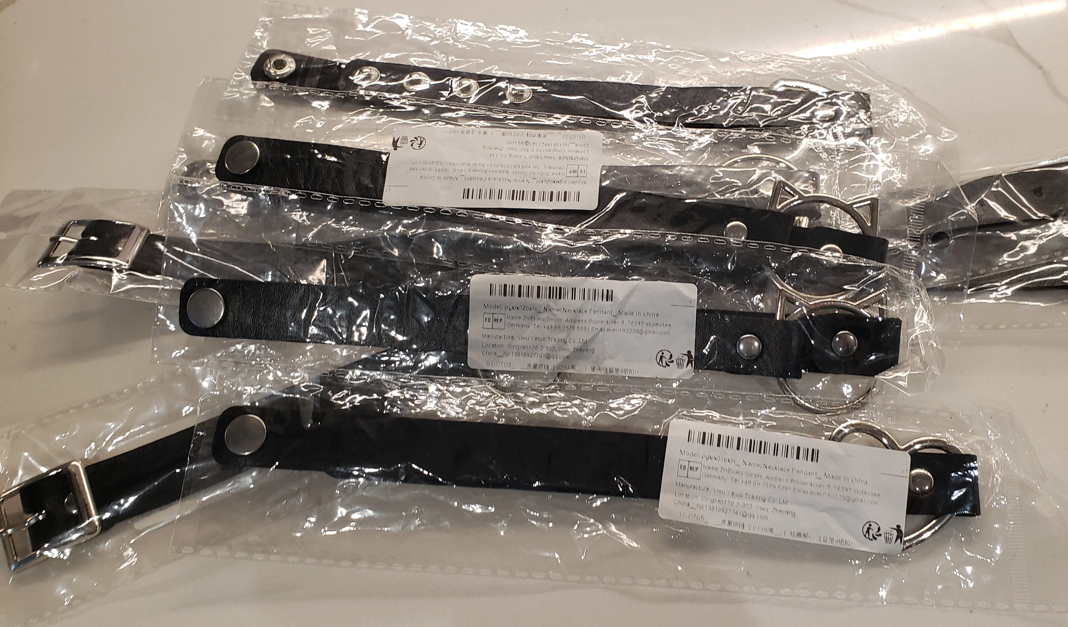
Assembly
Assembly wasn't too bad. It went something like this:
Solder the display connector onto the PCB. This was very finicky and I spent a long time fixing bad joints here. I should have bought a stencil ):
Solder three wires onto each side of the PCB for the LED strips. Add hot glue for strain relief.
Glue the board into the plastic case, letting the LED wires go through their respective holes. This was tricky - it was a tight fit and I had to bend the wires at some wild angles.
Remove the leather from an AliExpress choker.
Affix the leather to each side of the choker center piece.
Attach the 18650 to the leather.
Attach the LED strips to leather. They came with adhesive, but I added some super glue for a bit of extra strength.
Connect the screen, and glue it down.
The wires between the battery and the case were long and I decided to glue them to the leather. Normally I use hot glue, but I ran out and used superglue instead. I finished this Monday night (my DEF CON flight was booked for Wednesday). I figured I'd let the glue dry and went to bed.
Tuesday, after work, I checked on the choker. To my horror, the super glue had eaten through the insulation, exposing the bare copper underneath! This is very bad from a safety perspective, and would prevent me from using my choker.
I cut out the tainted sections of wire and replaced them. Luckily there was enough wire remaining to strip and solder - although it was close!
With that last-minute disaster sorted, I was finally ready for DEF CON.
Reception
I wore my choker, and cat ears, for Friday, Saturday, and Sunday of DEF CON. I wish I wore them on Thursday as well, but wanted to suss out the vibe first.
In short, people absolutely loved it. I got compliments all weekend, and it was really fun inviting people to draw on my neck. One failure mode I wasn't expecting was a lot of people thought it was a purchased product; many corrections were had (and people generally got a lot more interested when they learned it was DIY!)
The battery life was excellent. To be honest, I don't know how long it can last, because after a 16 hour day, the battery voltage is still solid at 3.7V. It's hard to compute lithium battery capacity from voltage due to how flat the curve is. I haven't tried running it for longer yet.
Speaking of the battery, it was very fun to twirl around to show people the 18650 strapped to my neck. Reactions were generally a combination of amused and horrified. But I didn't explode all weekend!
The weekend after was HOPE (Hackers On Planet Earth) and I decided to go with the same outfit there. Once again, reactions were generally extremely positive. I think this might just be my default attire for conventions/conferences now.
As it turns out, the touch screen doesn't work great when it's not coupled to the environment. It worked fine if e.g. plugged into my computer, but standalone it was almost useless. I found that I could get it to capacitively couple to my body via the 18650, which improved things, but it still wasn't amazing. In the future I would like to improve this.
As usual for me, the hardware and firmware are open source. The repository names are a bit of a misnomer; originally the software was going to be very generic and read frames/LED strip commands off of the micro SD card. Since I'm instead generating everything in real-time, changing the video requires changes to the code. I don't think this is a big deal but it's something that could be improved, and certainly makes the code specific to me.