Fully Preserving Fisher-Price Pixter TLDR: First ever complete reverse engineering, documentation, emulation, and preservation of all Fisher-Price/Mattel Pixter device series and [almost] all the games.
Table of Contents
- Pixter Color
- Pixter Multimedia
- Pixter Classic
- Starting with Pixter Classic
- The Weird Bus
- Dumping a Classic Cart
- Another damn VM
- What is "Native"? How do you define "Native"?
- Dumping the Pixter Classic ROM
- Identifying the SoC
- The BEX bus
- Melodies on Pixter Classic
- Programming the Pixter Classic
- The one weird pin on the cart
- Resistive Touch Panels on the Cheap
- Resistive Touch Panels beyond Cheap
- Pixter Plus and Pixter 2.0
- Preservation
- Downloads
- Appendix A - Pixter Color VM
- Appendix B - Pixter Classic VM
- Appendix C - connections and pinouts
- Comments...
Pixter Color
The beginning
In 2000, the famous American toy company Fisher-Price released a simple drawing-oriented handheld gaming console for kids called Pixter. It featured no brain-rotting social media and focused, instead, on drawing, sketching, and educational games. The initial sales figure from the holiday season of the release was half a million units, which is not too shabby at all. Besides letting kids draw using an included stylus on the 80x80 monochrome display while catchy tunes played on repeat from the speaker, the device also allowed plug-in games to expand the possible activities. There exist 25 known games for Pixter (I had to edit wikipedia to correct their record). Soon after, there was a Pixter Plus, which added more memory and expanded the built-in game. Then there was Pixter 2.0, which added wireless comms. Neither of those radically changed the device itself and all the games remained cross-compatible. One cool feature of Pixter devices was that you could draw an image in one game, using its stamps and tools, save it to internal memory, plug in another game, load it, and draw on top of it. So you could, literally, customize a cool car in "Cool Wheels", save the image, plug in "Barbie Fashion Show" and plop a barbie into your cool car image. What joy this must have been!
In 2003, Pixter Color came out, adding color, 4x the screen resolution, and a new game cartridge connector. An adapter came with it to allow it to run old games, and it ran them all (pixel-doubled) perfectly! Obviously, the old monochrome Pixters could not run new color games. The main purpose of the device remained the same - sketching and stickers with ability to save your compositions in memory, just in color now! Games got more advanced and intricate. There was even a camera attachment! There are 32 games known to exist for Pixter Color. In 2005, Pixter Multimedia came out, which added a better screen (quality-wise, the resolution remained the same) and a yet another game cartridge connector (a superset of the Pixter Color connector), allowing for Multimedia-only carts. Nine of these Pixter Multimedia exclusive game are known to exist.
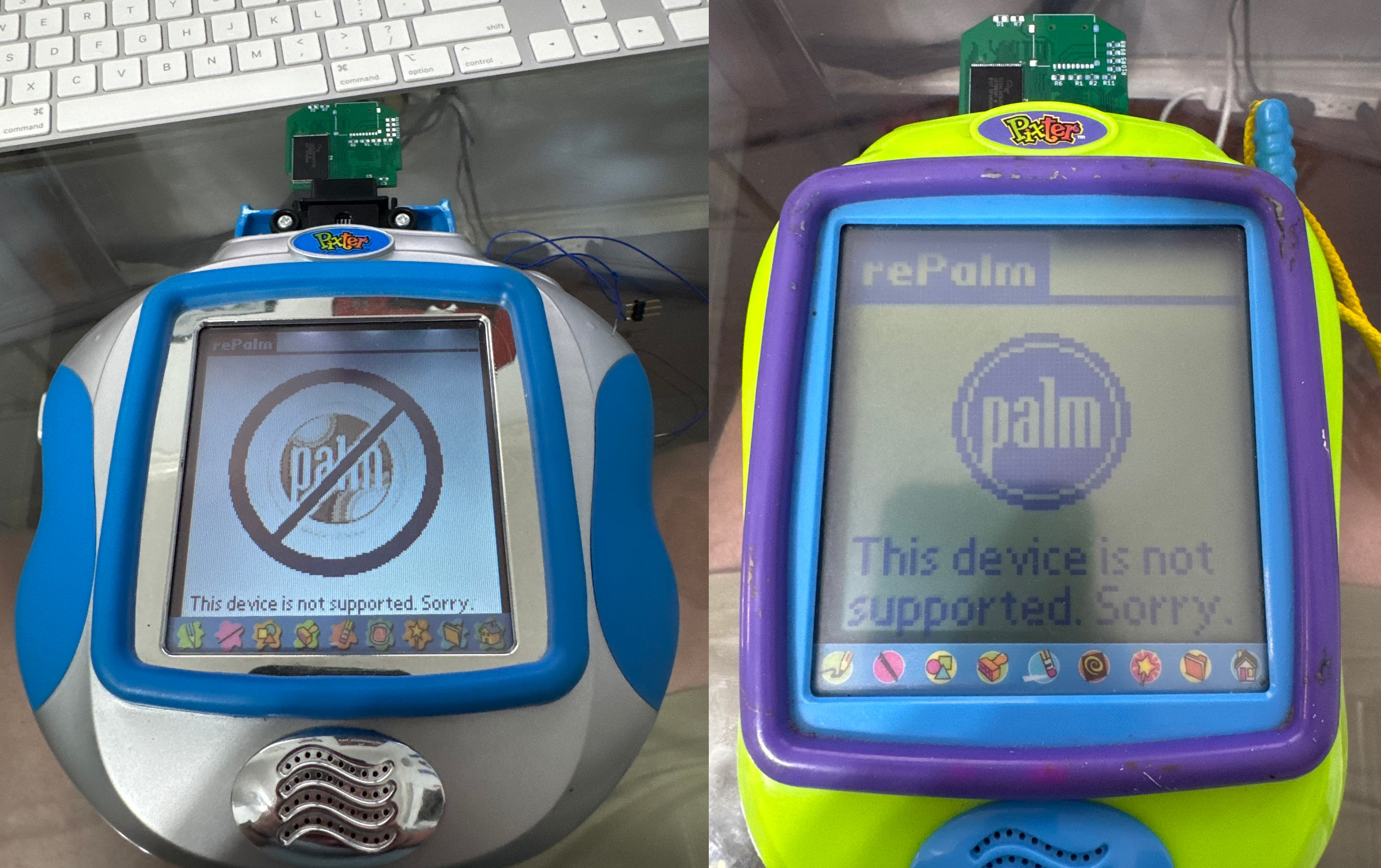
As I had written before, my friend Josh pointed me at Pixter Color as potential PalmOS porting target, and after a lot of work, I got PalmOS fully working on that device. This is not that story, however! To get PalmOS working, the device had to be understood, a method to run code on it had to be found, and among all that research, a lot of work was done on documenting Pixter Color. Previously, a few places online mentioned that “THERE ARE CURRENTLY NO EMULATORS FOR THIS DEVICE OR PLATFORM. ANY CLAIMS TO OFFER THEM ARE SCAMS!”. This is no longer true, I am happy to report. I am here to present a complete historical preservation of all information pertaining to how Pixter devices work and almost all the games. However, let us go in order...
Sometimes, you get lucky
| Pixter Color Slot | ||||
| 1 | A0 | || | 2 | D0 |
| 3 | A1 | || | 4 | D1 |
| 5 | A2 | || | 6 | D2 |
| 7 | A3 | || | 8 | D3 |
| 9 | A4 | || | 10 | D4 |
| 11 | A5 | || | 12 | D5 |
| 13 | A6 | || | 14 | D6 |
| 15 | A7 | || | 16 | D7 |
| 17 | A8 | || | 18 | D8 |
| 19 | A9 | || | 20 | D9 |
| 21 | A10 | || | 22 | D10 |
| 23 | A11 | || | 24 | D11 |
| 25 | A12 | || | 26 | D12 |
| 27 | A13 | || | 28 | D13 |
| 29 | A14 | || | 30 | D14 |
| 31 | A15 | || | 32 | D15 |
| 33 | A16 | || | 34 | PE1 |
| 35 | A17 | || | 36 | PE0 |
| 37 | A18 | || | 38 | nCS2 |
| 39 | A19 | || | 40 | nCS3 |
| 41 | A20 | || | 42 | nOE |
| 43 | A21 | || | 44 | nWE |
| 45 | A22 | || | 46 | PG6 |
| 47 | A23 | || | 48 | PD0 |
| 49 | PD2 | || | 50 | PD1 |
| 51 | PD4 | || | 52 | PF6 |
| 53 | PD3 | || | 54 | PF4 |
| 55 | PD5 | || | 56 | AUD |
| 57 | PD6 | || | 58 | Vdd |
| 59 | Vss | || | 60 | ?? |
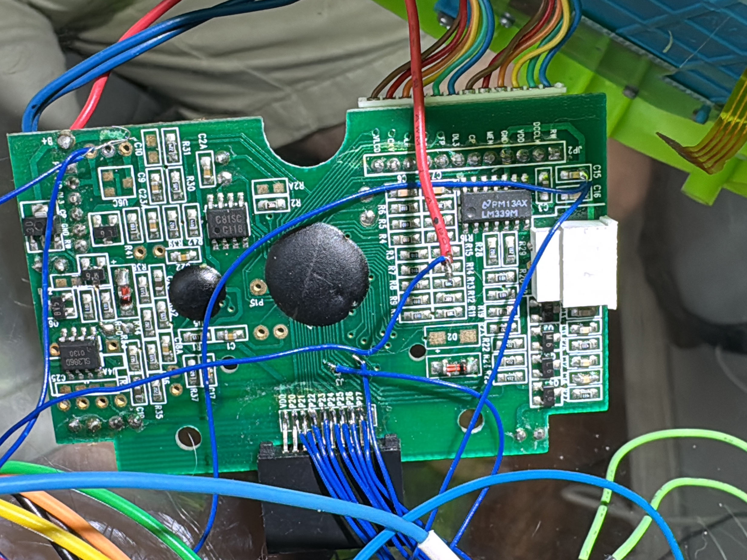
As there were no official docs on writing Pixter games or code, the first step of the process was to open a Pixter and see what was inside. It would later turn out that starting with Pixter Color was quite lucky -- its main SoC is the LQFP version of Sharp LH75411. Why is this lucky? Unlike other chips and chip package types, this specific one makes probing individual pins trivial, allowing even careful soldering to them. No other Pixter-family device has this property, but I did not yet know this.
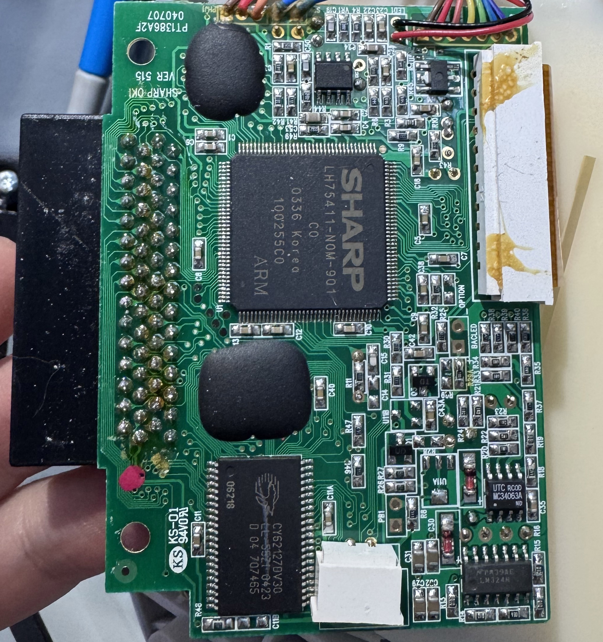
The main board had the main SoC, 128KB of x16 SRAM, and two black blobs. The blobs are of course Chip-on-Board dies of some sort. These are not labeled nor can they be easily probed. In most cases removing the epoxy is destructive. Black blobs are the worst! Sadly, they are common in cheap devices, and Fisher-Price were always kings of cost-cutting. As I went through this project, I, in fact, gained more respect for their cost cutting abilities than I had had before.
First, it is worth taking a moment to talk about the LH75411 and the surrounding chips on the Pixter Color motherboard, from a performance standpoint. I ranted about it already in my PalmOS-on-Pixter article, but in case you missed it, I'll summarize. This is the most minimal ARM7 instantiation I've ever seen. Everything that was optional was excluded, everything that could be sized was configured in the most minimal configuration. The SoC has 16KB of TCM inside, which is pretty fast - single cycle access in fact. There is also another 16KB of SRAM in the SoC, which is accessed using an internal AHB bus, meaning that reads effectively take 2 cycles. There is some SRAM on the board, as I had mentioned - 128KB on a 16-bit-wide bus. It is configured with one wait state (an extra clock of delay to allow signals to propagate and slow/cheap memories to process). A word read from this memory thus takes two bus operations, each using 3 cycles. This is getting slow, as you see. Luckily, this is where cache comes in handy. Cache automatically stores recently-accesses memory close to the CPU for fast access, covering up for high-latency and/or low-bandwidth memory.
At least, it would, had Sharp (the manufacturer of the SoC) bothered to instantiate some cache in the chip. There is none. This is not nearly the end of the performance troubles though. The ROM is also on a 16-bit-wide bus, though luckily without wait states. Due to this, fetching 32-bit-wide ARM instructions would be painfully slow, and almost all of the code in the ROM uses the 16-bit Thumb instructions -- a problem not unlike those faced by Gameboy Advance programmers, and for the same reason.
ARM processors use a table of vectors to handle interrupts and exceptions. The table can be located at one of two addresses: 0x00000000 or 0xFFFF0000. The first option for the address is also the value of NULL, and preferably, there should be no memory at that address to allow easy detection of logic bugs. The problem is that it is uncommon for SoCs to place memory that high in the address space so as to have anything at 0xFFFF0000. Luckily, an MMU can be used to map virtual addresses to physical addresses, and 0xFFFF0000 is a virtual address. All that is needed is to enable the MMU and make the mapping.
There is no MMU in this SoC. Well, OK, fine, I guess we are stuck with vectors at zero, but while an MMU does take up some silicon area and would make the chip slightly more expensive to make, ARM had designed a much simpler option - an MPU. It does not map memory but it allows setting various protection settings on some ranges of it. The Pixter ROM could then configure the memory at 0x00000000 to be only accessible by supervisor mode, and run all software in user mode, thus still trapping accidental NULL accesses. The MPU is such a small cost to implement that of course it should be present, even the very-cost-reduced ARM chip in the NintendoDS has this option enabled.
There is no MPU! There is also no alignment checking, no cp15 coprocessor, no ... anything that is optional at all. Just a chip full of "no". The practical upshot is that it is easy to crash this thing and not even know you did. It will also never be fast. Fine, it was meant to be cheap, not fast or stable. Let's see how the system works...
Show me the code!
I painstakingly dumped a cart's ROMs in a way that I thought would work. This is of no difficulty, once you source the proper $10 ea(!!) connector. Since I knew that the SoC is ARM, I opened up IDA Pro and loaded a game cart ROM. Out of the 2 megabytes of ROM, only about 300 bytes were recognizable ARM or thumb assembly. The rest either looked like bitmaps, or looked like nothing recognizable at all. It lacked the entropy to suspect that it was encrypted or compressed, and anyways the CPU would not be fast enough to support such a scheme. Whatever it was, it surely was not ARM code. Weird... Maybe I had a bad dump? Redoing it proved that I did not. Maybe this one game was weird? Checking another dump showed even less ARM code. Very very strange. At least the first few bytes always matched, which is plausibly the header. Clearly, I was not going to get anywhere that easily. It was time to dig deeper in.
The device can operate without a game cart at all. Thus, clearly, the main SoC needs to boot from somewhere if there is no cart inserted. Itself, the SoC has no flash memopry inside. As there are no other things on the board that can store code, I was forced to conclude that one of the black blobs was a ROM or a Flash CoB (chip-on-board). Not great... Tracing out the traces on board proved that the larger one is indeed wired up to the address bus, the data bus (all 16 bits), and the 0-th chip select line, precisely as one would expect the main ROM to be. So.... How does one read out a blob?
I’ll answer the question with a question: why do they call it a memory bus? Because it is a bus. All the memories are on a shared set of address and data lines. Each one gets its own “chip select” line, all other lines are shared. So ... if I could keep the main SoC from booting to stop it from getting in the way, solder a wire to the 0-th chip select line (nCS0), solder wires to the nOE and the nWE control lines, and then solder wires to the 24 address lines and to the 16 data lines, I could read out the blobtacular ROM. What could be easier than perfectly soldering 43 wires in close proximity? Actually many things, but this turned out to be unnecessary. Buzzing out the connections of the cart slot, it is trivial to find that all the address and data lines are represented there. The convenient part is that those pins are much more spread out than the pins on the main chip itself, making the job easier. Now, it should only be a matter of properly sequencing reads to the blob-ROM chip from a Pi Pico 2. Right?
They say that every complex problem has a beautiful, elegant, easy to explain solution that ... does not work... just like this plan... It so happened that while this SoC is kept in reset, it does not release all the bus pins to float freely as ... all other SoCs I ever encountered do. Luckily, this only affected nOE, nWE, and nCS0, and desoldering just 3 pins carefully is not too hard. That being done, the ROM was dumped. You can grab a copy here. By seeing at which address the ROM repeats, it is easy to conclude that the blob ROM is 2MB in size. That is a lot, but then again, that must include all the graphics, sounds, and logic for the built-in sketch-and-sticker activity, right?
Analysis of the Pixter Color ROM
There are good news here! There is ARM code. Not a lot of it, but a few hundred kilobytes is present. This is much better than a few hundred bytes that each game had. I went off to disassemble the code. Since the LH75411 has no MMU, there is no possible address translation, which makes it easy to sort out at what address this code is meant to live. By referencing the LH754xx User Guide, we know the precise address at which nCS0 (the ROM) is -- 0x40000000. We also know that nCS1 (the onboard RAM) is at 0x44000000, nCS2 is 0x48000000, and nCS3 is 0x4c000000. By tracing the copper on the board we know that nCS2 and nCS3 are wired to the cart slot. By tracing the copper inside game carts, we know that nCS2 goes to the ROM in the carts (blobtacular too, of course). This means that any addresses in the 0x48000000-0x4bffffff range are accesses to the game cart, and looking for that in the disassembly would be a quick shortcut to find out what the hell was going on here...
And find out I did...
The logic was right there, in front of my eyes, but I refused to believe it. Who would do this on an already-very-slow SoC with no cache? Why? But there it was...Fetch a 16-bit value, dispatch on the top few bits, there, dispatch on a few other bits, and there do some operations, jumping back to the beginning in an infinite loop. Some of the operations were weird - including unbalanced stack operations - pushes and pops. It was bizarre. If the code did not look otherwise correct elsewhere, I would have assumed I had dumped something wrong. But it all looked correct. This thing implements a 16-bit virtual machine, being interpreted by the ROM code. The unbalanced stack operations are ... because it is a stack-based virtual machine, and it uses the ... host stack to implement the VM’s stack. No overflow protection, no nothing - ruthlessly efficient and lacking any adornment. This is what Brutalism would look like if it were software. The VM manages to execute most simple opcodes in a dozen cycles or so, which yields about 4MIPS of computation. Curiously, while this is a 16-bit VM, there are in fact no limits placed on each stack-pushed value being only 16 bits wide -- all values are pushed as 32 bits wide. This leads to a lot of easy ways to cause unexpected behavior by pushing values over 16 bits in size and calling opcodes ill-equipped to handle them. Clearly security was not a concern, nor was stability, and honestly, that is fine. This was a single-purpose system and most games, I think, were first-party. I’ll allow it.
The weirdness gets weirder...
There were many signs that this VM was modeled after some real 16-bit processor, or some previous 16-bit VM that was actually pushing 16-bit values. How do I know? There are a few opcodes that are meant to operate on 32-bit quantities, and they always pop two values off the stack when that is needed. But since ARM is 32-bit, they just use one and ignore the other. On a real 16-bit device, you would indeed see two pops, but they would need to be combined. And if this were not modeled after a 16-bit device, there would be no reason to push two values when one would do. Given this, I spent a lot of time trying to locate hardware architectures or software VMs that use this set of opcodes. Sadly, I came up with nothing.
My theory is that before they settled on an ARM SoC, they considered some 16-bit architecture, implemented this VM on it, developed some games, and then switched to ARM. Fearing that they could break logic they are not aware of when it comes to how many values are on stack, they simply converted every push and pop into ARM equivalents, leading to 32-bit values using two stack slots, even when one could accommodate them just fine. Allrightly, so what does this instruction stream look like? Opcodes are always 16-bits in size and little-endian, most of them doing basic ALU things, and one group of 128 implementing Pixter-specific things like drawing and touch.
Those opcodes are prety high-level including things like playing an ADPCM sound, drawing a complete image with transparency, or sorting out which UI button a pen tap was targeting. Cool. I decoded them enough so that one could implement a high-level emulator of Pixter and run games in it. And this is not merely ravings of a lunatic. Once I realized that enough was decoded to do this, I shared them with Nathan Korth, who took on the task, and has produced some pretty cool and very promising results. I have placed more-or-less complete docs of the Pixter Color VM in Appendix A below for you to peruse. Enjoy.
Dumping the Color Carts
Now that I had some basic idea of how it all worked, it was time to start dumping more game carts. I dumped the few that I had on hand using my favourite multitool - Pi Pico 2. Due to the number of pins required to read out the entire x16 flash interface, I dumped in two passes, first the low byte of each word, then the high. The dumps were post-processed on my computer and looked pretty good, but how could I be sure? It is not like there is a Pixter color emulator out there to try them in.
Getting Emulation Started
Indeed there WAS no Pixter Color emulator. Over a few weeks, I added LH75411 support to uARM - my ARM emulator. I emulated all the required hardware blocks of the LH75411 and attempted to boot up the Pixter Color ROM, without any carts. This is perfectly fine since Pixter Color boots into a built-in game that allows sketching and stamping if there is no cart inserted. Fun story - this game is in fact written in the same VM as all the cart games, which is kind of cool.
It did not, of course, work right away, but eventually it worked. As usual, sorting out the resistive touch panel orientation and the range of correct ADC values took a while, but soon enough, it worked! I could now sketch things on a Virtual Pixter Color, and stamp smiley-face stamps all over my sketches! After some work, I even hooked up audio to verify that it worked, which it did, in a way. This emulator, greatly expanded, will be touched upon later, and is published here today!
"Audio" Playback
Pixter Color does not have a traditional audio codec, or really any sort of a proper DAC at all. Two PWM units in the SoC are used to output sounds to a speaker, via a cheap audio amplifier chip. The way the two PWM units are used is quite curious. How would you do it? Well, normally one would use a single PWM unit fed with unsigned samples, AC-coupled to an amplifier. That is indeed a sane way to do it. If you wanted more output swing, you could use two PWM units, one outputting an inverted signal, but as there is an actual amplifier, this would be a waste of effort. How best to use two PWMs units then? Well, you could use them to extend your range. As it happens, these PWMs are configured with a period of 128, and thus this are effectively 7-bit DACs. 7 bits is not much for audio, so you could scale the output of one by 1/128, mix it with the other, and thus get 14 bits of output resolution for better quality. I've seen this done before with great success. There are a few other options too, with varying trade-offs.
Pixter Color does none of the sane things. Instead, I suspect that its designers fundamentally misunderstood PWMs, audio amplifiers, and ... life. Every audio sample is evaluated. If it is positive, it is used as duty cycle for PWM0, while PWM1 is set to duty cycle of 0. If the sample is negative, PWM0 is set to a duty cycle of 0, while PWM1 gets the sample (negated) as its duty cycle. Then, PWM0's output is fed into the audio amp's positive input, while PWM1's into the negative input. Effectively this just gets them one extra bit of output resolution, at a cost of confusing the fuck out of us all, overcomplicating the code, and accomplishing little else.
Considering that all these audio machinations happen in an interrupt handler at 8KHz on a slow ARM SoC with no cache, where every cycle counts, I cannot justify any of this at all. My guess is that someone who had never dealt with audio read that an amp has a negative input, and instead of simply tying it to GND decided they need to provide it some input ... and did.
Melodies
My emulated Pixter Color worked well. Dumped games as well as the built-in ROM game worked well, but while the audio effects were there, the ever-present background music was missing. I went looking and found nothing wrong in the emulator. I also found no trace of any such music in the cart ROMs. Considering how long some of the songs were, I would have expected them to take considerable space, and yet they were nowhere to be found. I knew for sure that there were no more ADPCM playback paths and no more methods of outputting analog values out of the SoC. It had to be something else. It was time to, once again, trace copper on the motherboard. What else went into the audio amplifier?
Communicating with the Melody Chips
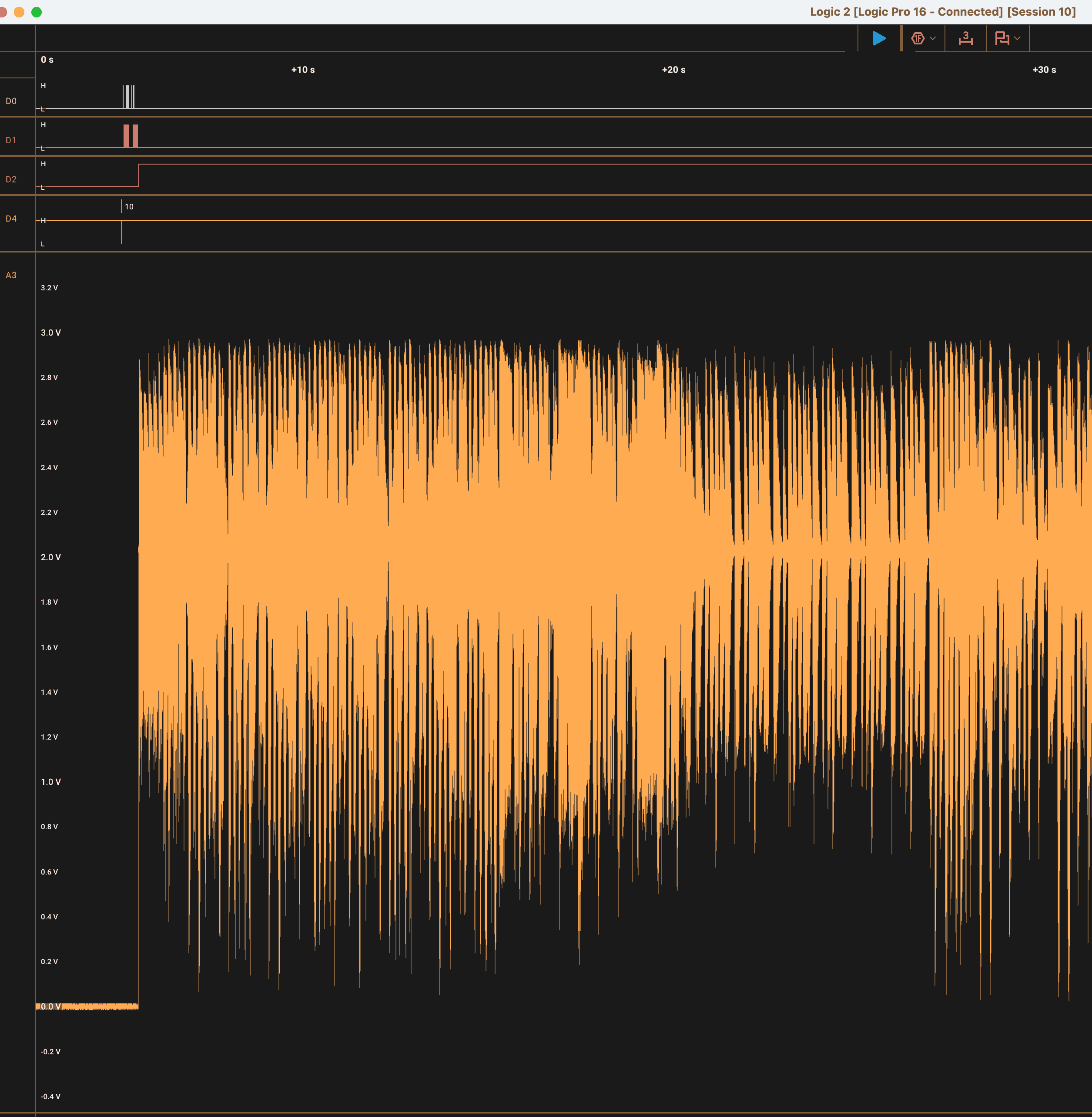
The second black blob on the motherboard connected to the amplifier, as did one of the pins on that cart connector (pin 56). Both were also pulled down to ground with 620 ohm resistors. Well, this is a bit weird, but not all that hard to check. I connected my trusty Saleae Logic Pro to the blob's output(?) pin and captured some analog traces as the Pixter played the background music for the built-in activity. Well, I'll be damned! There was my music! This blobtacular chip was producing music, somehow! When a game cart was connected, the audio came from pin 56. That explains why most carts had at least two blobs onboard - a ROM and a Melody Chip. The music sounded very MOD-like - it was some sort of a collection of samples that could be played back at various rates to vary the pitch and mixed a few "instruments" at a time. But there was no code to send notes to anywhere that I could find. What gives?
The blob chip onboard had only a few traces going to it, as did the ones in the game carts. Capturing them was not very difficult. It turned out that a two-wire interface controls the Melody Chips. And besides the audio output it had one more output - a digital one that was high while playback was ongoing, and low otherwise. Two control wires, so logically they'd use some sane two-wire protocol, right? Maybe it is bidirectional UART? Nope! Perhaps i2c then? That one is also nice. Nope! Well, OK, the Melody Chip probably does not need to reply to anything, so maybe it is simple clock and data, a-la SPI? Nope. That would make too much sense, definitely not allowed!
The protocol is a godawful design that features requirements to maintain tight timings while also providing no edges for proper signal capturing. What more could one ask for? I designated one line as "clock" and another as "data", because one was used as a clock and the other as data, more or less. They idle low. Before a command is set to the chip, the lines must be idle for at least 20ms (determined experimentally -- value may only apply at room temperature, 1atm of pressure, moon 3/4 full, mercury in retrograde). After that, a start signal is sent. To send the start signal, the data line needs to go up for 16 ms, then go down and wait another 16 ms. Clock stays low this entire time. After this, the bits are sent, MSB first. How many bits? Well, this can vary, as per disassembly. At least 4 bits are needed to represent a valid command. The top bit (sent first) is high to loop playback. This means playback will not stop until a new command is sent - when the melody ends it will restart. The next two bits sent are volume with 0 being the lowest (which is still audible, not muted), and 3 being the highest. The remaining bits (at least one) are the melody index to play. The last melody index representable in whatever bit length is used is reserved and must not exist. Thus it is used to stop playback.
In Pixter Color, there is a setting that the game must set using the SET_UI_SETTING opcode to tell later PLAY_AUDIO opcodes that target the Melody Chip how many bits to use for MelodyID. In reality, almost all games use very similar Melody Chips and use 6 bits for Melody ID, allowing for 63 possible melodies and thus using 9-bit-long commands. No game features that many distinct melodies, though. This also explained why GPIO PF6 is often checked by the games via the GET_MISC_SETTING opcode. It may seem obvious to you with the docs I am providing, but to me it seemed quite non-obvious at the time. The built-in game instead checks PF1. It is checking the "is playing" state from the Melody Chip. The external one in the cart is connected to the cart slot pin 52, which is indeed wired to PF6. The internal one inside Pixter Color is wired to PF1. It all makes sense.
Capturing the Music
At this point in time, my project goals had expanded and now encompassed properly emulating Pixter Color and preserving its entire game library for posterity (how can we, as a civilization, afford to lose such era-defining games as "Barbie Fashion Show"?). I had already dumped many carts, and Josh was scouring eBay for more, buying them, and sending them to me to be dumped. And I had just learned that all of my dumps made up till now had been incomplete. I had dumped the digital parts of the games -- the ROMs, and could emulate them, but the melodies were in an entirely different place that I did not and could not reach easily. I searched and searched online for any company that made chips that did any such thing with similar interfaces, but found nothing. I suspect these are likely very cheap 8-bit MCUs with large ROMs and some hardware assistance for music-production. Really all that would be needed would be 8 PWM units, maybe with DMA feeding them, and an 8051 core. In any case, they had no external wires that could possibly be used for programming, and the protocol did not seem to have any way to read them out. Digital capture of the source material seemed unlikely, although I would love to have one of these decapped and imaged, just to see what the hell it is anyways.
My first attempts to command Melody Chips in carts proved to be fruitless. The active line went high for the correct duration, but the output line would float around 3.3V and only show a few mV of ripple -- no sign of music. I beat my brain against this for a while, until I decided to try doing it while the cart was inserted into a Pixter Color. "What was the logic behind that?" you might ask. Unknown unknowns. I knew of no logical reason that this should matter, but I did not know that I knew of all the things that might or might not matter. I was still powering the cart's Music Chip externally, of course. What happened? Music! Remove cart - no music. Re-insert -- music still playing. What gives? Using kapton tape I started isolating pins and eventually got to a point that only two pins needed to be connected to the Pixter Color for audio to work - the audio out pin and ground. What the hell? I started tracing out the motherboard again. I had forgotten that a few weeks ago I wondered why there was a random 620 ohm resistor from that pin I had not yet understood to ground. That pin was audio out. I added a 620 ohm resistor to my dumping rig and audio flowed out. Evidently the audio chip is so cheap, they could not be bothered to put a full complementary pair of transistors to drive the output, there is only a transistor to pull the output up - it needs an external pulldown to work. Well, there were a few days I won't get back!
The audio quality in Pixter is not exactly symphony-hall-like. So I decided to simply command each cart's Melody Chips to play each melody in turn, capture them at the analog output, and be done with that. Just like numbers have a concept of "significant figures", audio should (if it does not yet) have a concept of "significant quality". If this does not exist, I hereby propose it, and propose to measure it as a value approximately equal to the sampling rate times the sample bit depth squared. Why this aside? Because there is simply no point capturing chiptunes played via a cheap speaker at 96KHz with a 24-bit ADC. Medium-quality-at-best audio deserves medium-quality-at-best capture. I captured the audio at 22,050KHz, 12 bits per sample using my trusty Pi Pico 2. The captured tracks were volume-normalized and downconverted to 8 bits per sample, producing a reasonable size capture. I went over all the carts again, dumping their audio this time. A few gave me troubles, but that is a story for later. As each cart had a different number of melodies of different lengths, dumps become different sizes at this point in time, having all previously been precisely 2MB or 4MB.
Internal Melodies
There is a Melody Chip inside the Pixter Color itself too. It plays the melodies needed by the built-in game. Capturing its melodies was a bit harder, since I could not simply command it from an RP2350 as I could a cart's Melody Chip. I first thought I could write a very simple Pixter VM program to play them, but after checking the disassembly, I noted that the VM will only play melodies from a cart's Melody Chip when a cart was noted to be the source of the VM program, and will only play melodies from the internal Melody Chip when the internal game is the VM's program source. So, there was no simple way for an external cart VM program to play an internal Melody Chip melody. Pity. Well, option two it is -- a simple cart VM program that escapes to native ARM code, and then twiddles the GPIOs manually to ask the internal Melody Chip to play. That works and the melody plays. Cool! But where to capture it? The simplest option, of course, would be at the speaker, but this would be after amplification and addition of the noise of the very very cheap amplifier chip and whatever other sources of noise there are. I, instead, soldered a wire to the output trace of the black blob, and then wrote code to play each melody in turn, wait for the "is playing" GPIO to go low, and then play the next. I captured the whole thing (digital command lines and analog output line) using my trusty Saleae Logic Pro 16. I exported the analog capture into a CSV file, processed using a script to normalize and cut into tracks based on the Melody ID in the digital capture, resampled to 22,050 samples per sec, and converted to unsigned 8-bit samples. The final result - melodies form the Pixter's internal Melody Chip are captured. Since the Console ROM is stored in the same PCI file (more on that in "File format" section) as dumped games, including the melodies in there was trivial.
The Strangely Good Screen
At some point during this work, I did encounter a Pixter Color with a strangely good screen -- too good, in fact. After it failed to boot my PalmOS build, my suspicions were confirmed -- something was different. The device actually did boot, based on the UART log from my PalmOS build, but the display was not working. Since it booted, I was able to get it to dump its own ROM to the SD card without any of the machinations that were needed to dump the initial Pixter Color ROM back in the beginning, what with the trace cutting, wire soldering, and the agony. Much more civilized: write one tiny PalmOS program, make it auto-run when SD card is inserted, wait a few mins, grab file from SD card. Awesome! The dumped ROM differed in only a few ways, all of them having to do with the screen initialization. Looking at what was being configured in disassembly, I realized that it is configuring the screen as a TFT, not as an STN. This would turn out to be the same screen as the Pixter Multimedia has.
Pixter Multimedia
| Pixter Multi Slot | ||||
| 1 | A0 | || | 2 | D0 |
| 3 | A1 | || | 4 | D1 |
| 5 | A2 | || | 6 | D2 |
| 7 | A3 | || | 8 | D3 |
| 9 | A4 | || | 10 | D4 |
| 11 | A5 | || | 12 | D5 |
| 13 | A6 | || | 14 | D6 |
| 15 | A7 | || | 16 | D7 |
| 17 | A8 | || | 18 | D8 |
| 19 | A9 | || | 20 | D9 |
| 21 | A10 | || | 22 | D10 |
| 23 | A11 | || | 24 | D11 |
| 25 | A12 | || | 26 | D12 |
| 27 | A13 | || | 28 | D13 |
| 29 | A14 | || | 30 | D14 |
| 31 | A15 | || | 32 | D15 |
| 33 | A16 | || | 34 | PA5 |
| 35 | A17 | || | 36 | PA4 |
| 37 | A18 | || | 38 | nCS2 |
| 39 | A19 | || | 40 | nCS3 |
| 41 | A20 | || | 42 | nOE |
| 43 | A21 | || | 44 | nWE |
| 45 | A22 | || | 46 | ??? |
| 47 | A23 | || | 48 | PA0 |
| 49 | PA3 | || | 50 | PA1 |
| 51 | PB6 | || | 52 | PA2 |
| 53 | PB7 | || | 54 | PH3 |
| 55 | PB0 | || | 56 | AUD |
| 57 | PB1 | || | 58 | Vdd |
| 59 | Vss | || | 60 | ?? |
Pixter Multimedia was a followup on Pixter Color. It used the LH79524 SoC, which was the followup on LH75411. This one, luckily, has an MMU and cache. Now now, contain your excitement, it is just 8KB of cache, and there is still the 16KB of eSRAM, so the total amount of SRAM in the chip dropped from 32KB to 24KB, but the cache covers all memories, and thus helps performance a lot. This is not even negated by the lower clock rates! The board has 4MB of SDRAM on board as well, which is super nice. There are also some buttons: a 4-way pad and A/B buttons. The display is a TFT which means that it actually has contrast, viewing angles, and can show colors other than washed-out-grey and blurry-ish-brown-ish which were all that the STN screen in Pixter Color could manage. The SoC can actually display 65536 colors onscreen, though due to how it actually works, 32768 is more realistic. While literally everyone in the world and their grandma all agree that 16-bit-color means RGBA565, LH79524 asks you to hold its beer and goes for XRGB1555. The top bit acts like the LSB for all channels at once. So indeed it can show 65536 colors, but any sane use of the chip would simply ignore that top bit. Well, who needs compatibility after all?
There is a real audio DAC onboard as well, so that now DMA can be used to playback real audio. Most of this hardware was well utilized by my PalmOS port to the device. It has the same slot as the Pixter Color and runs all Pixter Color games. Its slot, though, has a cutout, which allows Pixter-Multimedia-exclusive carts to be inserted. Those have a special plastic protrusion on their cart which prevents their insertion into the Pixter Color. A few Pixter Multimedia exclusive carts are known, and most featured video content.
Those special Pixter Multimedia carts are curious in their own right. First of all, they are the only cart type so far that has no Melody Chip inside. Secondly, their interface and command set are precisely what you'd expect of NAND. They use the existing cart data bus (D0..D7) as the data interface, and three more pins (57, 53, 51) as control signals. None of the carts I saw had actual NAND, though I imagine for development such carts existed. They all used a chip from a company called Matrix Memory. They specialized in read only memory that was NAND compatible. I guess we finally know what a sample use case for read-only-NAND might be. These carts were the largest - 32MB or 64MB each. They were also the easiest to dump using my trusty Pi Pico 2. It was only a matter of 13 wires and a bit of time. I dumped not only page data but the "spare area" that all NAND chips have. Matrix Memory chips seem to report all spare bytes as 0xff.
As NAND does not allow direct execution, how do these games work? Well, this is why Pixter Multimedia has 4MB of SDRAM. The cart header is much simpler here, and it basically just describes an offset and a length for data to be read out of NAND into SDRAM and then jump to. The header details are in Appendix A. Once this first copy is made, it usually takes over the device and loads more data from the cart to SDRAM. None of the Pixter Multimedia titles use the Pixter Color VM. They are all native code, and based on the strings I found in them, they all use Micrium RTOS. There are no ROM routines that they use. Once the cart is loaded, no more accesses to the ROM are observed, it is a complete device takeover. Well, why not?
I did create my own version of this too. I implemented a build of PalmOS that boots entirely in-RAM on the Multimedia. It works pretty well, as expected. I have it load from cart, and the cart can then be removed.
There is, however, an internal Melody Chip in the Pixter Multimedia, and its melodies were captured using the same method as the ones in Pixter Color were.
Pixter Classic
Starting with Pixter Classic
Pixter Color was merely the first of two second-generation Pixter devices. Long before it, there was the first generation, comprised of three devices, each an upgrade(ish) on the last. Pixter Color can play their games in a backwards-compatible way, but they cannot play its. There was no reason to exclude them from the newly-expanded scope of preserving all things Pixter.
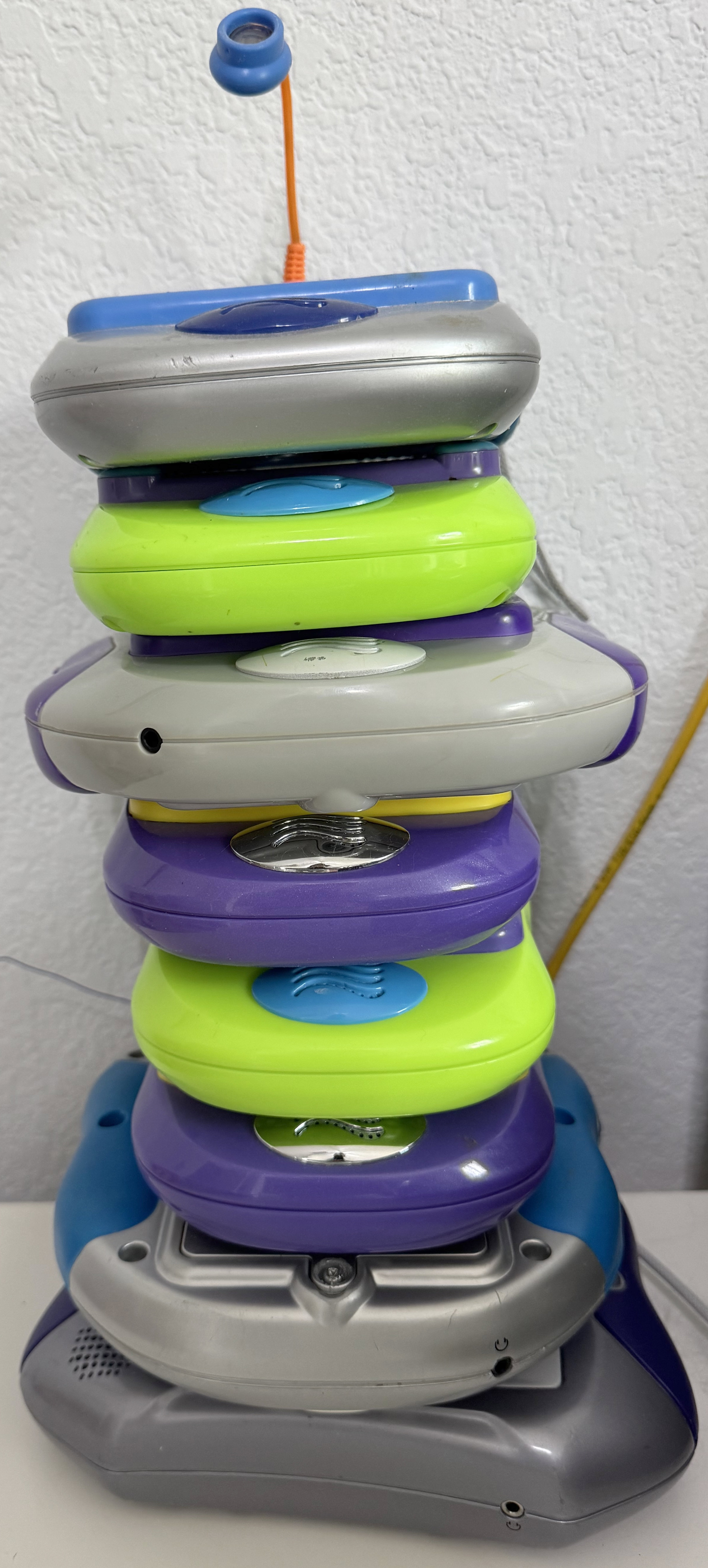
The first Pixter was simply "Pixter" and it featured an 80x80 monochrome black and white display, a resistive touch panel on top of it, and a tethered plastic stylus with a hole to tuck it into. The base activities were the same as on Pixter Color - sketch things, stamp things, and draw things while catchy music plays in the background and sound effects of "splat" are heard as you stamp something with a stamp onscreen. I can only imagine how much less fun this was on a black and white screen without even any shades of grey. Inside, it only has black epoxy blobs. Not promising.
Pixter Classic also supported game cartridges and a number of games existed. The cart slot is similar but much shorter -- 20 pins instead of 60. The pinout (now that I figured it out) is shown in Appendix B. But initially I did not know the pinout, of course, and I was rather confused. The games were quite rich, with lots of sounds and graphics. I was not sure what sort of an interface would support that over only 16 pins (what is left after removing "power", "ground", "audio out", and "audio active" from 20). Even if the interface was only 8 bits wide instead of 16, once you add in nWE, nOE, and nCS, there are only 5 bits left for address, allowing addressing of only 32 bytes - definitely not enough. Yeah.... The bus had to be multiplexed in some way. This was also difficult to believe -- multiplexed busses are not common on simple systems nowadays.
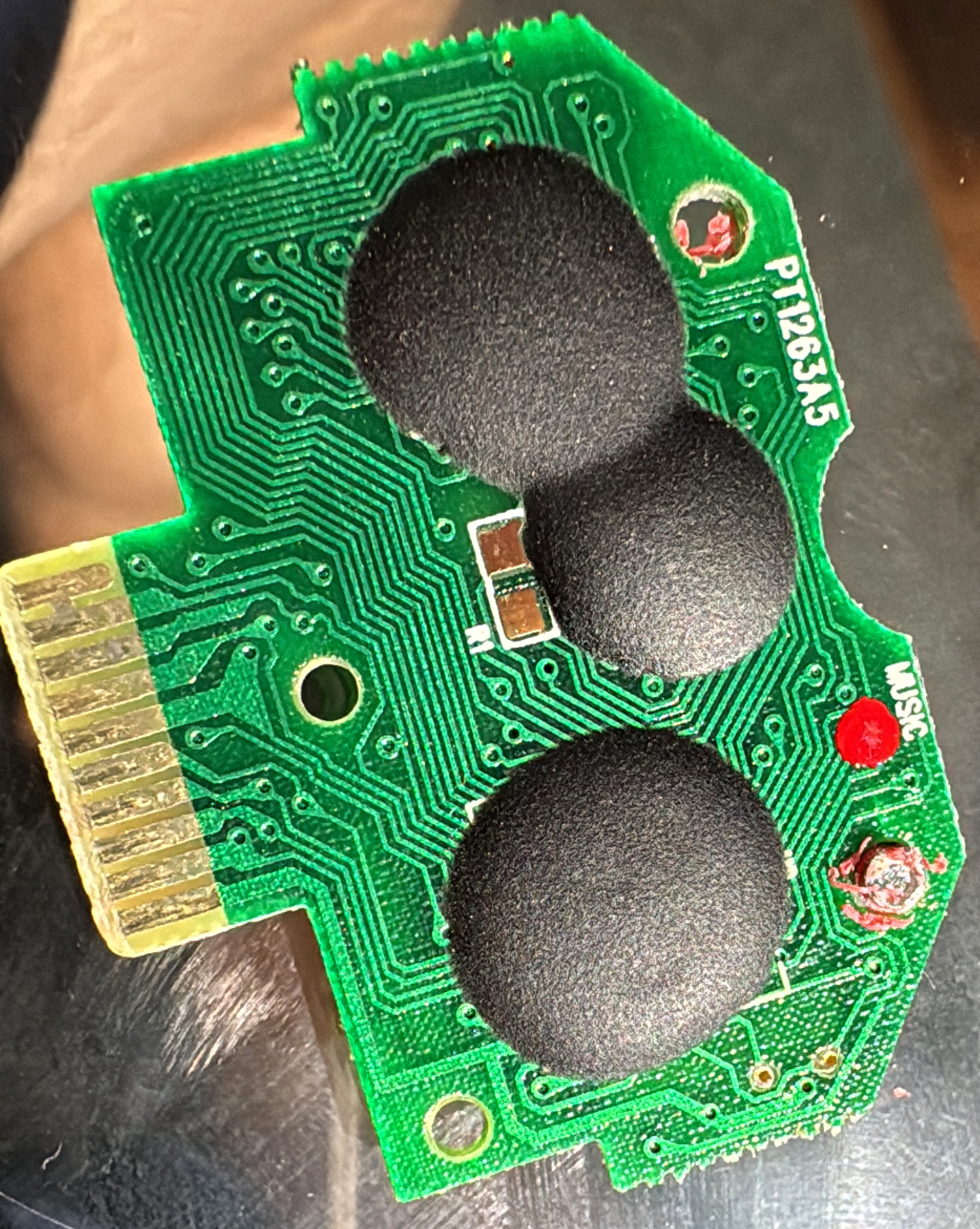
Luckily, since Pixter Color can run Pixter Classic games, I could disassemble Pixter Color ROM some more and see what it does. But where to even find the code that handles this? The existing VM code only read its instructions from 0x48000000, and we already concluded that the connector was too narrow to fit a real parallel bus. There is, however, even more luck to be had here. Pixter Classic carts connect to Pixter Color via an adapter. I had a bunch of them, so it was not at all troublesome to cut one open and see what is inside. Maybe there is a chip that talks over the x16 parallel bus on one end and on some weird bus on another?
The cut-open adapter revealed no chips, no passives, no anything -- just plain copper wires. Most of the 20 pins from the Pixter Classic connector were wired to pins on the Pixter Color side. The wiring is detailed in Appendix C. To my great surprise, some of the 20 pins were not connected at all, indicating that even fewer than 20 pins are actually used! Curious. The next thing that is notable is that none of the Pixter Color-side pins used were address or data pins of the parallel bus. Clearly some other interface was used here, and Pixter Color clearly spoke it natively, no magic chip in the adapter. The pins used were all GPIOs, some in port C, some in port D, some in port E, and some in port F. No rhyme or reason as to which as far as I could tell. But I had a lead! Either those pins were uses as GPIOs and I would see them twiddled with code, or they were used as some ... function, in which cease I would at least see them configured as such and would get a hint of how they work based on the function used.
The Weird Bus
The pins were used as GPIOs. I found a function that took an 8-bit value and wrote each bit of it unto one of 8 GPIOs all of which were used by the adapter. It was often called from a few places, each of which before and after it, after some delays, twiddled two more pins. There were two of those wrapper functions. One accepted a 16-bit value and an 8-bit value, it wrote the high and then the low bytes of the 16-bit value to the GPIOs, with intermittent toggling of other pins, then wrote the 8-bit value to the GPIOs and twiddled the other pins some more. The other one accepted a 16-bit value, also wrote the high and then the low bytes of the 16-bit value to the GPIOs, with intermittent toggling of other pins, then READ the same 8 GPIOs in the same order and assembled a byte out of them, and then twiddled the other GPIOs some more. Do you recognize what it happening here? We have an 8-bit-wide multiplexed bus with 16-bit address and 8 bit data, where two control signals are used to set bus operation/state!
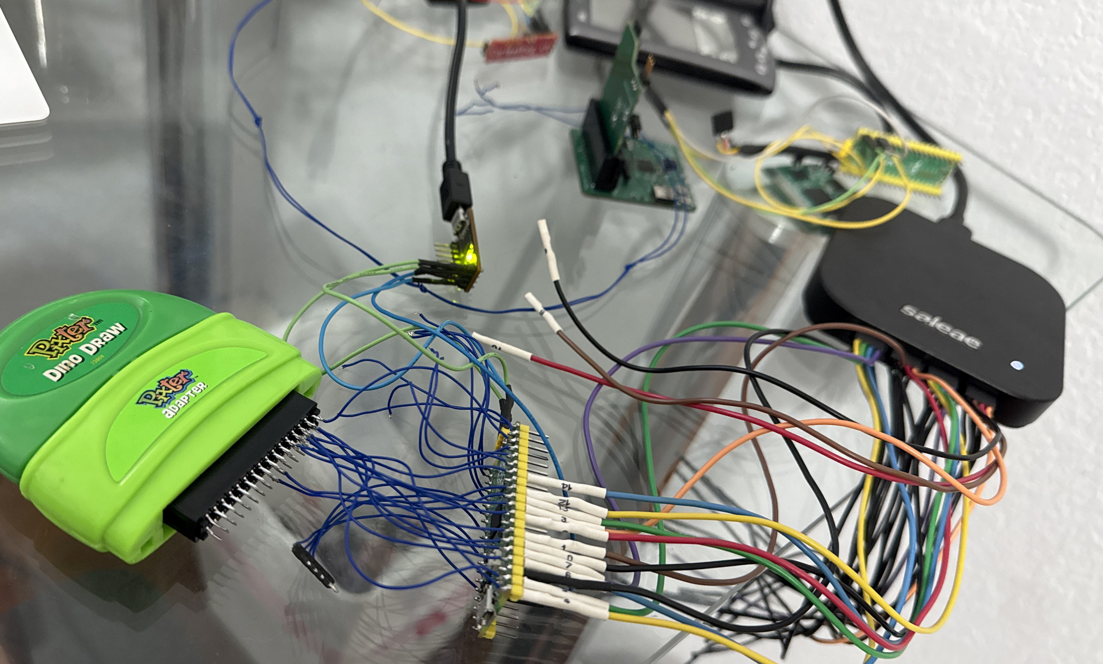
OK, so what kind of bus is this? I searched in vain for anything that looks like this and found nothing. I would eventually find docs for this bus and even learn that I understood it perfectly from my reverse engineering, but this was quite a bit later. I had to figure it out from the code at first, and from bus traces. Anyways, I arrived at the assumption that those two functions were effectively u8 bitbangedBusRead(u16 addr) and bitbangedBusWrite(u16 addr, u8 val), I first sought to understand the bus, so that I could capture it with my Saleae Logic analyzer for better analysis. There were two control signals used, clearly, they are labeled E0 and E1 in the pinout and most of my notes. Why? Because they are GPIOs 0 and 1 in port E on LH75411 in the Pixter Color and I needed to give them a name! The 8 data pins are labeled DQ0..DQ7, and sorting out which GPIO was which pin was easy from seeing which bits of data went to which one.
The control lines idle high. Here is how a READ bus transaction looks: first, the high 8 bits of the address are put on the bus, after a small delay, E0 is taken low and another small delay is observed. Then the low 8 bits of the address are placed on the bus, now E1 is taken low while E0 is taken high. Another small delay is observed. Then the bus is put into input mode, data is sampled, and then E1 is returned to the high state. The WRITE transaction is similar: first, the high 8 bits of the address are put on the bus, after a small delay, E0 is taken low and another small delay is observed. Then the low 8 bits of the address are placed on the bus, now E1 is taken low while E0 stays low. Another small delay is observed. Then the data value is driven onto the bus, and after a small delay, E0 and E1 are both taken high, returning the bus to idle. So pretty much it is clear that: On E0's falling edge the high byte of the address is sampled. On E1's falling edge, the low byte of the address is sampled, shortly after that, E0 can be sampled to determine if this is a read or a write. Based on that, the bus is either driven or read by the target. It is all nice and clean except for that "small delay" part. It is not at all clear when the bus turns around from being driven to being read. But since the bus is driven pretty slow (3MHz), capturing it and making sense of it was not too hard.
I made a number of captures and the results were bewildering, there was traffic on the bus with reads and writes showing nonzero values even when there was no cart inserted. However, there was a lot more traffic when a cart was inserted than when one was not, so I captured a number of instances of both, cleaned up the data, calculated the differences and found what I believed to be the reads targeting the cart. The first two were reads of two bytes that looked like magic values from 0xbf00. The values were 0xAA, 0x55. Now, I was getting somewhere! But where?
Dumping a Classic Cart
The bus was understood. It was time to dump a cart. At least so I thought... The cart did not reply to my bus access cycles, despite the timing perfectly matching the Pixter's when accessing it. What gives? I captured analog samples and verified that it was not driving the bus at all during my read cycles. It was ignoring me! How dare it?! I guess that there was some init sequence that was necessary. There was no way to know which of the transactions I saw on the external bus were necessary and which were not, which pin toggles were needed and which were not. The latter was solved by kapton tape-ing over contacts and seeing if the cart was still detected. The former... well I just captured all the transactions before reading of the magic number from the cart, and then replayed it using my Pi Pico 2 to a cart. Huzzah! It responded and the magic number was readable!
Well, the address space is 64KB, let's dump it all. Here, things, again, went sideways... Reads in the range 0x0000 - 0x1fff mostly produced a floating bus. Reads in the range 0x2000 - 0x3fff produced data in some carts and lots of 0xff in others. Reads in the range 0x4000 - 0xbfff produced plausible reproduceable data in all carts, and reads in the range 0xc000 - 0xffff produced a floating bus. What does this say? It looks like only 40KB of the 64KB address map has data, sometimes only 32KB. That seems VERY little to store a game with sounds and images. There must be something more here! Even I am not good enough to fit Cool Wheels into 32KB with audio effects and all those car parts. But...the magic number was there, which means my reads were working.
Another damn VM
Back to the Pixter Color ROM I went, to see what it does with those Pixter Classic games. Now that I knew what the bus operations looked like, I was able to find the code that read the magic number, and the code that followed if it was found. Before long, it was another "fetch-dispatch-do some things-fetch again" loop. Yup! Another VM! This one used 8-bit instructions and 8 bit data. Again, it is clear that stack layout was a concern, and thus even though (again) the host stack was used to represent the VM stack, 32 bit quantities were pushed when only 8-bit values were used. Again, no masking was used so it is possible to confuse the VM in a number of ways. Some things in this VM were reminiscent of the other one, but it is definitely simpler. I guess the story here is that Pixter Classic used this VM, and it was deemed insufficiently powerful for color games, necessitating a new VM be designed. However, for backwards compatibility, all new color devices needed to support the old VM to run old games. That all makes sense.
I detailed the new VM in Appendix B, there is more than enough detail to implement an HLE, and Nathan Korth is already on it. Same as before, much of the decoding space was used by normal ALU operations, and a smaller amount was used by very complex operations like image drawing and sound playback. Image compression differs, of course, since compression of monochrome images is necessarily a different beast compared to compression of color images. The audio format was still ADPCM, with the same decoder being used. Curiously, there was an option to play back ADPCM at sample rates other tan 8KHz, but I suspect this was never used in games and was thus removed from the Pixter Color VM's abilities. Comparing what the two VMs can do provides some intriguing technological archeology exercises, some of which I followed up on, and many more of which I leave to the reader.
KNOWN_GAME_ID
Before starting the Classic VM, the code first read a few specific locations (the initial PC value for the VM) in the cart ROM and then looked up their values in a table. If found, it then recoded the index in a variable I termed "KNOWN_GAME_ID". If not found, the value was set to 13, then it checked another location for a value of 0xAA, and if so, another table was consulted additionally. If there was a match there, "KNOWN_GAME_ID_2" was set to the index plus one, else it was set to 0. Why all this? The answer is obvious - clearly some games did some questionable things on the old Pixter Classic hardware that needed game-specific handling on the new Pixter color hardware. This is not unexpected, really. Backwards compatibility, given enough "backwards" and enough "compatibility" always ends up looking like if (app_is_x()) { allow_insane_thing_Y(); add_custom_handler_Z(); }.
It is worth remembering that in the Pixter Color VM, there were two opcodes that allowed the games to break into native ARM code. It would not be unreasonable to assume that that Pixter Classic VM has something similar. This is a great example of something that might need game-specific handling on Pixter Color. Why? If we assume that the old Pixter Classic did not use the same exact LH75411 SoC (which it very much does not), then native code for it might not properly run on Pixter Color. It is also logical that most games would have game-specific native code, and thus need game-specific handlers.
Native Callouts again
With a well formed theory that there is very likely to be an opcode that allows one to break out into native code on Pixter Classic, I went looking. Naturally, the place with the highest concentration of looking at "KNOWN_GAME_ID" was the place to look. I found it. For handling opcode 0x96 (now called NATIVECALLOUT) there was a complex dispatch table based on "KNOWN_GAME_ID" and then based on one of the values popped off the stack, making it look like it was customary for the native callout (or what I assumed was it) to have two parameters and one reply, with the first parameter being as selector and the second -- an actual parameter. But... what is this... it actually got a lot more interesting. There was a path through that table that resulted in running ACTUAL NATIVE ARM code. What?! Yup. To reach that path, the game had to have been identified as "KNOWN_GAME_ID" 13 which means that it is not known by the first table, the second lookup must also fail, setting "KNOWN_GAME_ID_2" to 0. If that is the case, the code path is taken that might lead to native ARM execution on Pixter Color. The first popped value (the selector) must be 0xc8. When that happens, a little-endian 16-bit value at cart location 0xbf40 is used as a source address, the little-endian 16-bit value at cart location 0xbf43 is used as end source address. Then, the byte-sized value at 0xbf42 is inexplicably written to address 0x0000 on the cart interface (I'd later learn what this is for, see appendix B). After that, the size described by the above-mentioned start and end addresses is copied from the cart to host's memory at 0x60003000. This is the end for this opcode. The code is not run... yet. To trigger that, we need another NATIVECALLOUT call. Here, the "selector" needs to be 0xc9 or greater. 0xC9 is then subtracted from it, and the result is left in r0. The code in RAM is then jumped-to. No checking is done if any code was loaded, you could be jumping to garbage. YOLO. On Pixter Multimedia, this works too, except 0xd0 is the value instead of 0xc9.
This indicates that some more Pixter Classic games came out after Pixter Color came out, they had (or at least could have had) native ARM code in them, and Pixter Multimedia needed to custom-support those selectors as the exact shipped code would not work on Pixter Multimedia. Cool - more digital archeology. Classic games I know to include ARM code: Monster Shop, Music Video Creator, Rocket Power, SpongeBob, Toy Designer, Word Factory. Curiously, all but the last two that list have the same exact offsets and lengths for ARM code: 50 bytes from page 0x0f addr 0x7f00. The code is the same too. It implements only two selectors (thus 0xc9 and 0xca). I'll let you explore it. "Toy Designer" has a more substantial ARM chunk at 784 bytes. It implements 5 selectors (thus 0xc9..0xcd). Also kind of cool. "Word Factory" features 336 bytes of ARM, implementing 7 selectors (thus 0xc9..0xcf). This effectively explains the 0xd0 in Pixter Multimedia's ROM and basically proves that NO Pixter Classic games came out after Pixter Multimedia was out, and that no Classic Game ever ran a single instruction of native ARM code on Pixter Multimedia (until I did, of course). Fear not! This was all only moderately reckless -- the Pixter Color ROM did have a table of function pointers to various useful functions at a hardcoded location, so the later TFT-screened Pixter Color with a slightly different ROM could still properly support this insanity.
What is "Native"? How do you define "Native"?
I still did not know what architecture Pixter Classic SoC was. I knew that there are not that many black-blob ARM SoCs around, and there were even fewer in the year 2000, so ARM was unlikely. This is made further likely by the fact that EVERY Pixter Color game used native callouts for at least a little bit of work. It is logical to assume that Pixter Classic games are similar. And yet, the halfwords at 0xbf40 were much more often 0xffff than not in the ROMs I read out. Earlier-released games did not have these at all. Of the 25 dumped games, only 6 had ARM code. So ARM native code is not common, and thus some other architecture must run Pixter Classic. But which? I did not have a way to read out Pixter Classic's ROM to try to guess it from that. Another approach was needed.
Let us reason logically. First, the VM must be implemented in code. Second, when the NATIVECALLOUT is run, it must somehow run native code. Third, the code must somehow come from the cart. Fourth, the game VM instructions also come from the cart. Fifth, I know how to snoop on that bus non-destructively. Hey, wait now! All I need to do is wait for a game to execute the NATIVECALLOUT opcode and see where things fetch from. I captured a long session of playing Action Art using my trusty Saleae Logic Pro. I then searched for 0x96 which is the opcode for NATIVECALLOUT. Many were false positives or address bytes and not data bytes, but eventually, I did hit upon a fetch that was definitely from the cart address space 0x4000-0xbfff with the value of 0x96. Before that, a few other opcodes were fetched, at about 200KHz rate each. Just after the fetch of NATIVECALLOUT, much faster reads from the cart came, for a few hundred bytes, then it was back to the sedate 200KHz fetches of the VM, resuming at the very byte past the 0x96 of NATIVECALLOUT. There it is, I found it! Indeed it was not anything from 0xbf40.
[0xBF0C] -> 4C 00 BD [0xBD00] -> A5 60 0A AA BD DE BC [0xBCE2] -> 3C [0xBD07] -> 85 62 BD DF BC [0xBCE3] -> BC [0xBD0C] -> 85 63 6C 62 00 [0xBC3C] -> A5 61 85 62 A9 A6 85 65 A9 28 85 61 20 FC BB [0xBBFC] -> A9 00 85 67 E6 67 F0 08
The sequence of bus reads I was looking at was bewildering. And you, dear reader, do you see it? I am willing to bet that anyone over the age of 50 who has played with home computers in youth will immediately recognize the bytes. I recognized them because long ago I spent a weekend writing an emulator for this specific CPU. Going once...twice...sold! It is 6502! Yes, that 6502. What is it doing in a blob-chip in a kids' toy from the year 2000, I did not [yet] know, but there it was. It seems like the VM's handling of NATIVECALLOUT on Pixter Classic is to jump to 0xbf0c. There, is expected an absolute jump to the real NATIVECALLOUT handler. I loaded the few carts I had dumped into IDA in 6502 mode, set up a proper memory map, and indeed, every time 0xbf0c had an absolute jump to a handler of some sort. Given the fetch rate on the bus, it looked like the toy was run by a 3MHz 6502. Some games, somehow, instead ran the CPU at 6MHz, which is pretty speedy. Compared to other old 8-bit designs, 6502 is actually relatively performant per-cycle. This is a nontrivial amount of computation ability. But still, this not the 1970s, what is the 6502 doing here, and what time machine did it crawl out of? Fair, there are some old cores commonly used today in cheap places, like the i-wish-it-would-already-die-but-it-will-outlive-me shitshow that is the 8051, but this is the first I've seen of a modern tapeout of a 6502. What. The. Hell?
Dumping the Pixter Classic ROM
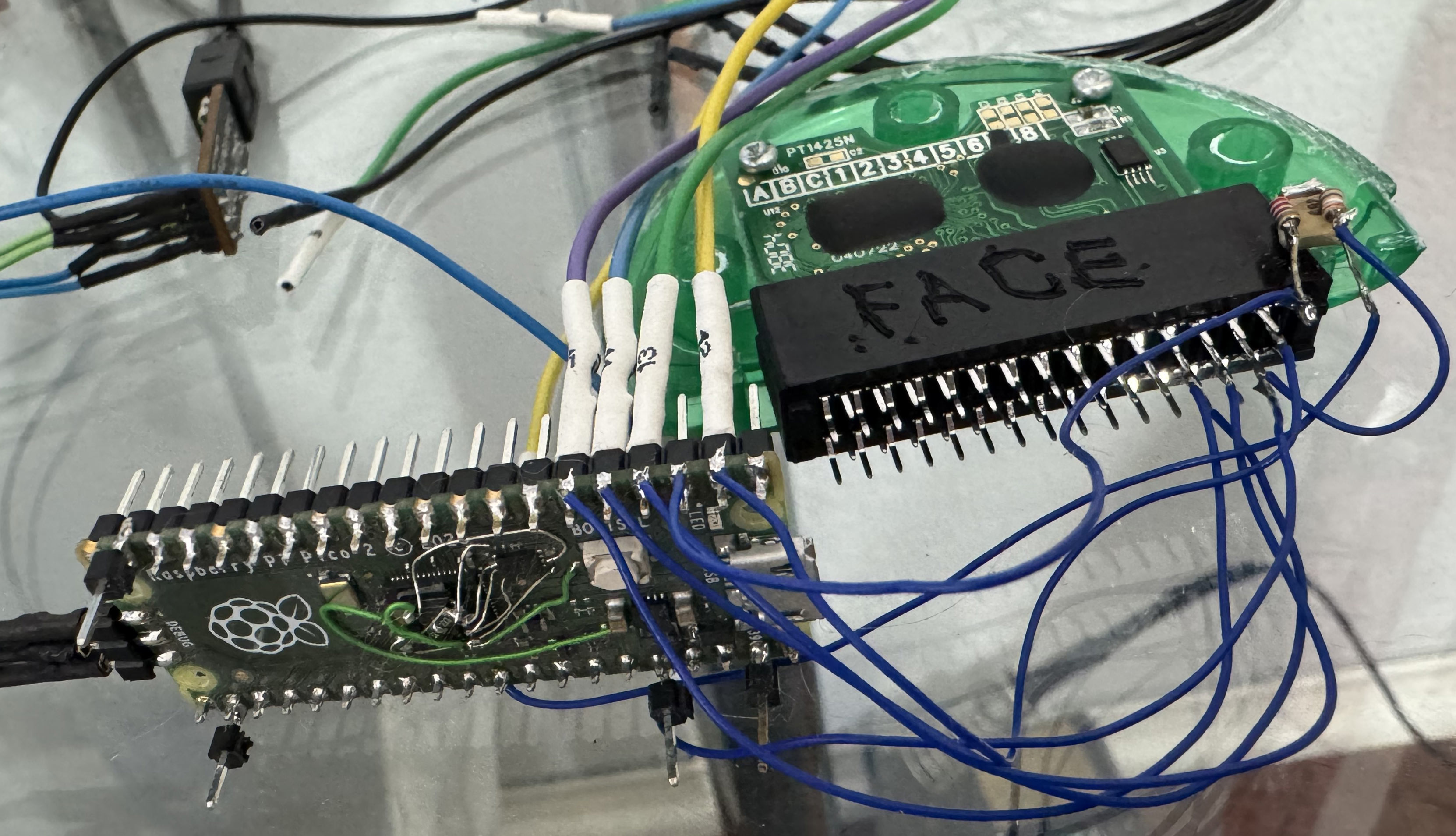
So how did I plan to dump the Pixer Classic ROM? Again, I used my Pi Pico 2. I programmed the PIO to properly act as a slave to this weird bus, and to reply as best as I knew how. After some debugging with my trusty Logic analyzer, It seemed to make the console happy, and it got past reading the magic bytes and on to more reads from the cart. At that point in time, it was a triviality to redirect the "initial VM PC" at 0xbf06 to a random address of my choice (in my case, 0xbf80), where I placed a single VM opcode: NATIVECALLOUT. I placed a valid 6502 JMP at 0xbf0c, jumping to 0xb800. There I placed some test code. Initially, it was just an infinite loop, to verify that I got that far (by watching the bus). I did. Next was the task of actually dumping the ROM.
How to output with no output devices?
I did not know anything about the SoC, so using a GPIO was out. I had no idea how to draw to screen, so that was out too. But, I could issue bus accesses! What if I dedicated a bus area only for this use and no other? I decided to use 0x8000..0x80ff. I would thus, in a loop, do *(0x8000 + *addr++). I would then capture the bus, filter for reads from that range, and get myself a dump. This was very very very fragile. Too fragile to work reliably, actually. I missed bytes sometimes and sometimes I saw accesses that were not mine. I guessed they were caused by some interrupt handlers in the Pixter Classic's ROM code.
*(0x80a0 + ((addr >> 12) & 0x0f)); *(0x80a0 + ((addr >> 12) & 0x0f)); *(0x80b0 + ((addr >> 8) & 0x0f)); *(0x80b0 + ((addr >> 8) & 0x0f)); *(0x80c0 + ((addr >> 4) & 0x0f)); *(0x80c0 + ((addr >> 4) & 0x0f)); *(0x80d0 + ((addr >> 0) & 0x0f)); *(0x80d0 + ((addr >> 0) & 0x0f)); *(0x80e0 + ((*addr >> 4) & 0x0f)); *(0x80e0 + ((*addr >> 4) & 0x0f)); *(0x80f0 + ((*addr >> 0) & 0x0f)); *(0x80f0 + ((*addr++ >> 0) & 0x0f));
I went with a slower but less error-prone option. I would, instead, emit a nibble at a time, twice for easier tracking. I would also emit the address, tagged as such, also twice. Basically, it looked as shown here. This is dense but simple. Now every access's address's low byte has a tag in the top nibble and a value in the bottom. The tag of 0x0a is "top 4 bits of addr", 0x0b => "addr bits 8..11", 0x0c => "addr bits 4..7", 0x0d => "addr bits 0..4", 0x0e => "data top nibble", 0x0f => "data bottom nibble", each being sent twice. This was slow, but I was able to capture a read of the entire 64KB address space this way, after a few tries.
Initial analysis
As expected, the address space contained the unknown things in the beginning, the cart ROM in the middle 32KB, and the Pixter's built-in ROM at 0xc000-0xffff. Again, I know there must be more to this, since the built-in game, its sound effects, and a whole VM will not fit into 16KB. However, I did have a lot of 6502 code to analyze. It is a start. Same as any other 6502, this one had vectors at 0xfffa: NMI vector, reset vector, and IRQ vector. Those looked sane. For some reason, there was a second set of vectors at 0xfff2. Analyzing those, it seemed like they were also: NMI vector, reset vector, and IRQ vector. Strange, but that can be dealt with later. I found the VM loop relatively easily, and from that, I was able to figure out most of the internal structure, since I knew what the high-level opcodes did. I found the memory buffers, framebuffer, etc. As a test I even put together a little 6502 demo that showed Conway's Life onscreen on the Pixter Classic, served from a fake cart that was really a Pi Pico 2.
Now that I had a handle on this thing a little bit, it was time to dig in more. Where was the built-in game? I found the code that read the magic number from the cart, and looked as to what it does when that fails. It then, still, read the address at 0xbf06, and still went on to interpret opcodes. That made no sense! That is cart address space, and that read would produce garbage with no cart inserted. How does this not crash? Then I noticed, that before reading the cart magic number, the value 0xc0 is written to the address 0x0000, and that value is not replaced if a cart is found and the VM runs cart code. If the cart is not found, before reading 0xbf06, the value 0x00 is written to the address 0x0000. Bank switching between cart and internal ROM? That could be. I searched the code and saw other values written to that register. In the irq handler, the value was read, replaced, and then restored, implying that it is important to current execution context. When that is done, it is often masked with 0xe0. All of this paints a picture: The low 5 bits of this register are a bank number, and the top 3 are a device selector. Or at least that is what I concluded. This might explain why writes to low addresses appear on the external cart bus - if there is bank switching, it must be done by the cart itself, and thus it must see those writes.
I modified my dumping tool to try to flip to the internal ROM before dumping, by writing 0x00 to 0x0000. No output. It took me a few hours of beating my brain against the issue until I realized that I was an idiot. My code ran from the cart, in that same address space. If my bank switch indeed worked, I would expect all further fetches to come from the internal ROM, and thus execute garbage, or perhaps not garbage but definitely not my code. As the idea hit me, I was able to trivially verify this - the external bus went dead after the write to 0x0000. Hmm.... Well, I knew where the framebuffer was in RAM, and I was not using it, so presumably I could copy my code there. Assuming some sanity in the device design, the framebuffer is unlikely to be banked and would thus be a good place for code that bank-switches. It did not work. I banged my brain against the problem some more until I realized that I was still being an idiot. If I switch to internal banks, my fake accesses went there too... I needed to switch banks back and forth between reading the ROM and emitting my fake accesses. This worked, and I was able to dump the 32KB of ROM that lived at 0x4000..0xbfff. Curiously, the bytes 0x4000..0x7fff were the same as 0xc000..0xffff. I then got more ambitious and tried pageflipping, dumping the full 64K of address space for every page from 0 to 31. This took a while but worked too....
How memory paging works
From what I figured out up to this point, there are 3 windows into ROM, each 16KB in size. WindowA is 0x4000..0x7fff, WindowB is 0x8000..0xbfff, WindowC is 0xc000..0xffff. There is a register at 0x0000 which I called BANKSEL. At any given point in time, WindowC shows internal ROM at offset 0x4000. What WindowA and WindowB show varies based on BANKSEL. The bottom 5 bits of BANKSEL select the bank (each 32KB in size). WindowA shows the higher 16KB of that bank, WindowB shows the lower 16KB of that bank. This explains, also, why the bytes 0x4000..0x7fff were the same as 0xc000..0xffff when ROM bank 0 is selected, and why 0xc000..0xffff did not change as I varied the bank index.
The top 3 bits of BANKSEL select the device to be mapped into WindowA and WindowB: 0b110 selects external (cart) ROM, 0b000 selects internal in-Pixter ROM. Given this, I re-dumped all the carts using my Pi Pico 2 setup, now dumping all the pages and finding out that most games were 512KB in size (except Word Factory which was 1MB). Now that I understood the addressing, I recombobulated the Pixter internal ROM, removing paging artefacts, and found it to also be 512KB in size. You can grab a copy here, if curious. Now I was mostly sure that these dumps were complete. The size matched with what they contained in terms of gameplay and sound richness. Fun sidenote: all VM code by necessity must fit in page 0. The VM always resets the page to 0 before reading code. Images, sounds, and other data may exist in any other page and are always addressed with a {page, offset} tuple.
Some fun to be had
Since native callouts differ between 6502 and ARM, it is possible to tell if you are running on an ARM or a 6502 Pixter. On ARM ones, there is a register that distinguishes LH754xx and LH795xx. This means that a single cart can behave quite differently based on the hardware. And indeed I implemented such a classic cart as proof-of-concept. On the black-and-white Pixters, it shows a black and white image. On Pixter Color, it shows a high-resolution color image, and on Pixer Multimedia, it decompresses its payload to internal RAM and boots PalmOS, since there is enough RAM. Source code for this perversion is provided below.
Identifying the SoC
While complaining about this unidentified 6502 to a good friend, he told me that there is a chinese company that makes cheap 6502s - Sunplus (later renamed to Generalplus). He told me that they are often sold as bare dies and would thus be seen in a product as black blob. Well, it could be... I went to look for a user's guide for some of these chips, but found none in the usual places. Google has gotten quite useless at actually finding anything nowadays, so this was not a surprise, sadly. Yandex to the rescue! I found a few datasheets and user's guides for a few different Sunplus 6502-based SoCs. Their memory maps kind of did fit what I was seeing. None were a perfect, but some were definitely close. Sunplus had chips with LCD controllers, like the SoC in question had, but not for the same row and column count. They had chips that did not support external bus that I knew this chip did have, and so on. But, in the end, I concluded that the Pixter Classic is built around a chip that closely resembles the GPLB3x series. There are differences. Pixter's SoC lacks nibble and mirror byte accelerators, which sucks, and it lacks SPI and watchdog features. The clocking is clearly different too, as is display control. Additionally, Pixter SoC's memory map differs a bit in terms of how the range 0x2000..0x3fff is treated. But having a vague but-somewhat-close-to-accurate user guide was a LOT better than having nothing. As the GPLB3x came out after Pixter Classic, the lack of a few of the cooler GPLB3x features makes sense. Pixter likely uses its predecessor, whatever that was called.
Now that I had at least some docs, I was able to sort out which GPIOs went where. It helps that many Sunplus chips are similar internally (as gleaned from very incomplete datasheets). I found which GPIO went to the "calibrate" button in the back, made it an output, and bit-banged 9600 baud 8n1 serial port out of it. Now I had a better way to talk to the outside world than my messy method of fake bus transactions. I no longer had to capture megabytes of data and postprocess them. I could just watch text scroll by in my minicom window! Creature comforts FTW!
I could run code and I could talk. It was time to experiment. I quickly tried various GPLB3x features to see which were present and which were not. I played with the register I thought controlled clocking (0x0004) and better understood it. The bottom 5 bits seem to always be written to 0b01100 but the top 3 bits seem to control the CPU clock divider from the RC oscillator that is used to generate it. The nominal RC clock rate in Pixter Classic is 6MHz, and the CPU clock is the RC clock divided by a value set by the top 3 bits of register 0x0004. It is not linear, and some values seem to simply halt the CPU. The values that work are: 0 (RC / 4), 1 (RC / 2), 2 (RC / 1), 5 (RC / 32), 6 (RC / 16). Most games run at RC / 2 = 3MHz. They can request double-speed if their carts support fetching at that rate. Internal ROM also runs ar RC / 1 = 6MHz.
The display controller was also quite unlike GPLB3x. Experimentation showed that the top bit of 0x0005 enabled the LCD, the lower 7 bits, when multiplied by 16 represent the framebuffer address in the SoC's RAM. If the resulting value is larger than the RAM amount in the SoC, it wraps around, as one would expect. I have no idea if this theory is correct, but all tests I did backed this theory. It is also possible that the mechanism is entirely different while the results are entirely indistinguishable from what I propose. In any case -- this is how it actually works. The register at 0x000E sets the number of display columns, when multiplied by 16. Pixter Classic configured it to be 5, as the display is 80 columns wide. Changing this to be less causes fewer columns to be driven, as one would expect.
GPLB3x-ness of the chip also explains the secondary vectors at 0xfff2. This is for factory testing, and tracing out that code actually helped me understand things a bit more. And of course this also explained the weird external bus.
The BEX bus
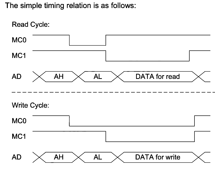
So, evidently this is the external bus that many Sunplus chips support. I did not find a name for it, so I am calling it "BEX bus" since its stated main purpose is "bus extension", often shortened "BEX" by Sunplus. This is a very very very poorly designed bus. Why? Observe that usually one would want to capture signals on edges. That makes digital design nice and clean, and allows one to not depend on random delays. From the diagram, it is clear that "AH" - address high byte is captured on the falling edge of MC0 (what I had called E0). That is good. "AL" - address low byte is captured on the falling edge of MC1 (what I had called E1). This is also good. But, if you are the master on this bus, when is it safe to sample the bus for a read? Who knows?! You do not know. It is NOT on the rising edge of MC1, cause you control that, and you do not know how much time you need to give the chip before then to produce the data! And for write, when will the chip sample the written data? Here, it might be argued that the rising edge of one of the MC signals is the proper time, but ... this is not what the chips do. If you try this with a BEX chip you'll end up writing garbage -- I tried. It is also not clear how soon after the end of a transaction it is safe to start another. I had to find out experimentally too. It turns out that data is valid and data is sampled "some time" after the falling edge of MC1. "Some time" is the equivalent of a recipe telling you to "add salt to taste"! It is meaningless, it is bad design, and Sunplus should feel bad! Fun side note: some later-found docs list some timings for the bus. Neither Pixter nor any carts meet them.
That being said, It is now clear why the init sequence was needed for the cart to start talking - it needed to be told its "Volume ID" in BEX speak. How do I know that? Carts just have two blobs, so how could I possibly know? Well, Sunplus have a chip you can buy that speaks BEX on one end and provides normal memory interface on the other. With some searching on Yandex, we can even track down a user's guide. Now, I have no reason to suspect that this is precisely the chip under the blob in the carts. Actually, I have reasons to suspect that it is not, but it is closely related and the registers all line up, and that is a help already! This chip supports a number of modes, detailed in Table 7.6.1 in the guide. Pixter Classic configures it by default for mode 0b110. These chips can also be chained, and this works - I experimented with this. Up to seven chips can be chained on the bus, each allowing up to 4MB of memory to be connected. It is rather fancy, in a perverted sort of way.
The way it works is like this: after reset, each BEX chip is in "initial" state wherein they ignore all writes except writes to address 0x000d. The first nonzero write that is seen to that address is absorbed by the first chip in the chain. It remembers this address as its VolumeID. It then releases the next chip in the chain from reset. The host can then issue a write to 0x000d again. The next chip remembers that new value as its VolumeID. Assigning the same VolumeID to multiple chips is not a good idea as their output drivers will fight and at least one chip will release the magic smoke. In any case, when a nonzero write to 0x000d matches a BEX chip's remembered VolumeID, it will consider itself active, while all non-matching ones will consider themselves inactive. As VolumeID is a 3-bit value, we get our 7-BEX-chip limit on the bus. Pulling the reset line low again will cause the first BEX in the chain to reset itself and pull its output reset line low, resetting the next one in the chain, and so on until they are all reset and ready to be reconfigured.
Acquiring a GPBA01B
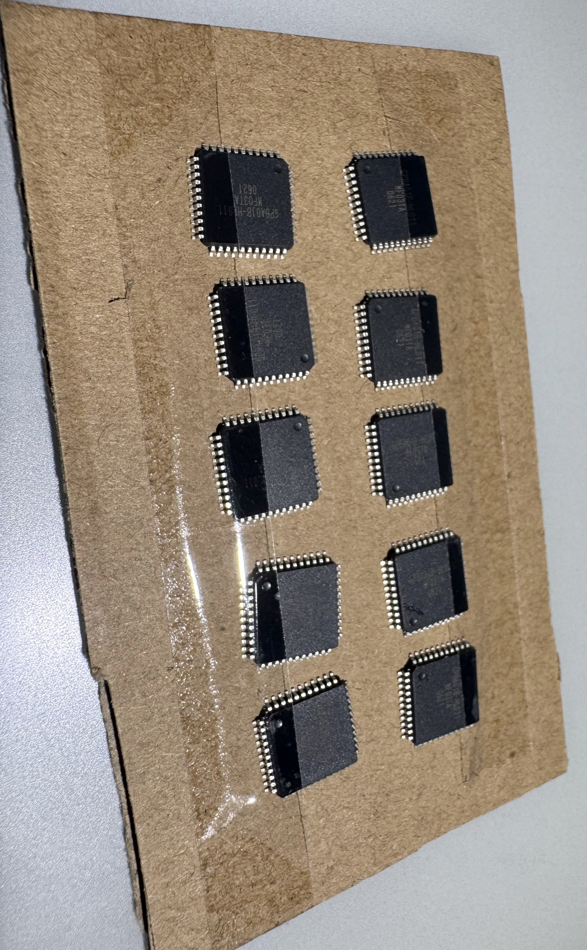
Sunplus say that this chip is only available as a bare silicon die, which you need to wire-bond to a board and put black epoxy over (making it a blob). But, for some reason, I found a random chinese website claiming to sell this chip in a TQFP44 package. Officially no such package exists for this chip, but I was curious enough to throw a few bucks at the problem to find out. As is usually the case with such websites, it is 50/50 if you ever hear from them after placing an order. In this case, I did hear back, with a message that "unfortunately the listed price was wrong and in reality it costs more". How fucking convenient! Somehow it never "unfortunately" costs less. Fine, I'll pay the extortion-level prices ($9 ea) just to satisfy my curiosity. The chips even arrived...eventually.
But what is the pinout? The seller, predictably, had no docs, and Sunplus do not even claim to have such a chip in this package. However, they do have a die photo in the datasheet, showing 44 wirebonding pads. Now, there is no reason to assume that the pin order of a 44-pin chip would map perfectly to the die pad order, but there is also no reason it would not - it would be the simplest thing to do. Still, that does not guarantee anything. However, it is possible to verify this guess nondestructively. To protect from electrostatic discharge (ESD) almost all modern chips have built-in diodes from every i/o pin up to VCC and down to GND. The idea is that any voltage higher than VCC will get clipped to VCC, and anything lower then GND will get clipped to GND thus avoiding bad things. By using the "diode" setting on a multimeter, one can thus find VCC and GND pins on most modern ICs by finding to which pins most pins have the same diode-voltage-drop. This check showed that a 1-to-1 mapping of die pads to pins is likely. George laid out a board, my favourite board house JLCPCB made the boards, and I built one. This board had space for an SD card (bit banged using free pins), 1MB of ROM, and 2x 1MB of SRAM.
Using the GPBA01B
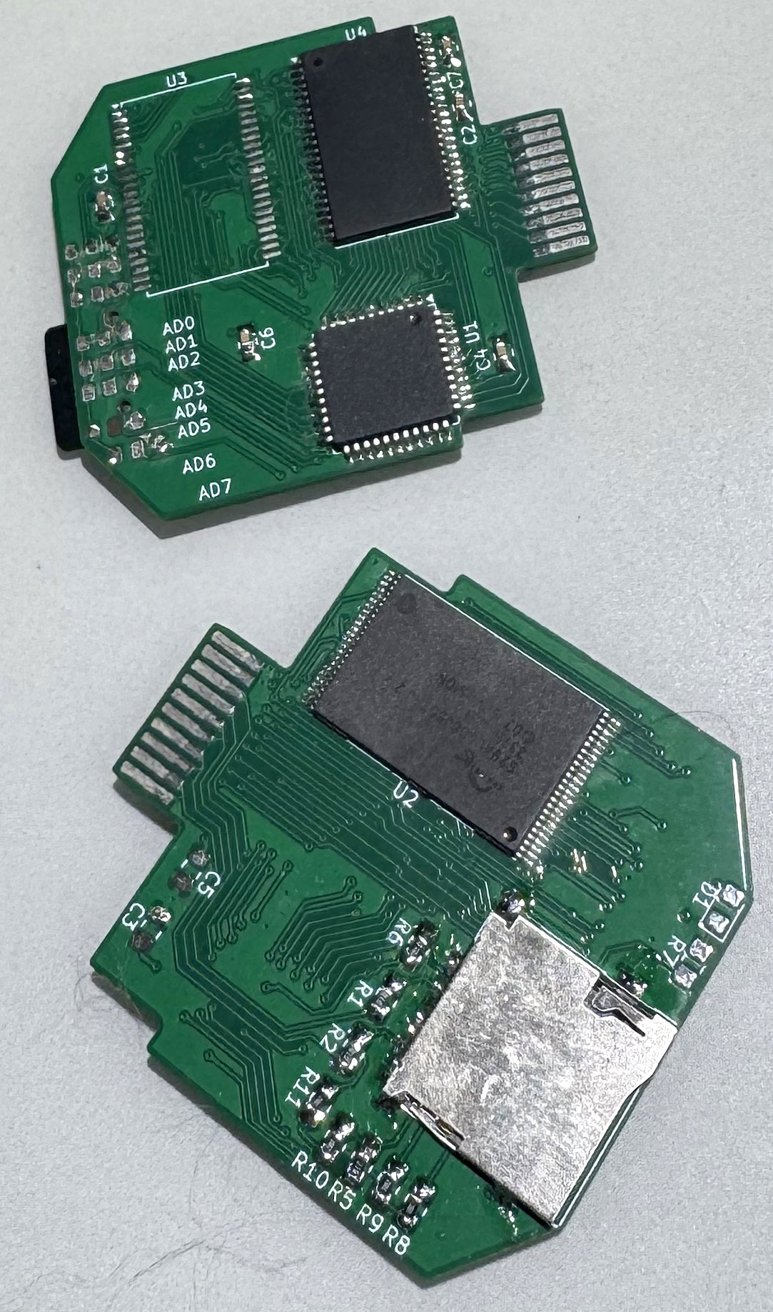
I soldered on a 1MB NOR flash behind the BEX chip. But how to flash it? My Pi Pico 2 to the rescue again! This time, instead of being a BEX slave, it is BEX master, and by issuing the proper BEX commands, flash writing commands can be issues through it. It works! George even designed a nice board to make this all easier for me to do! I wrote my dump of "Arcade" game to the NOR and the Pixter Classic happily ran it. The game worked! How cool is that? This proved that my dump was correct and complete, and that the grey-market BEX chip really works! It is notable that the game ran with sound effects but without background melodies, same as for Pixter color, melodies were yet a separate thing to handle...
The memory map documented in the datasheet confirms what I had deduced precisely, with one additional detail that I had missed. I did not know what 0x2000..0x3fff mapped to, and the datasheet for GPBA01B clearly states that in mode 0b110, it maps to "last 8KB of memory". It is fascinating to note that this line of documentation matches neither the game carts I dumped nor the chips I bought, and they mismatch identically! In dumped carts, 0x2000 always mapped to 0x7a000 offset into the flash (24KB from flash end). In the chips I bought, it mapped in the same way. Why does this extra mapped window matter? Many games run without emulating it at all, but some break quite spectacularly. We'll get back to this later.
Melodies on Pixter Classic
I expected the Melody Chip to work the same way on Pixter Classic as on Pixter Color. Why would it not? Since I knew which opcodes in the Classic VM were used to start melody playback from my Pixter Color ROM disassembly, it was merely a matter of finding the handling for those opcodes in the Pixter Classic ROM. The code distinguished whether we are playing a game from the external cart or from the internal ROM. For in-Pixter ROM game, the Melody Chip (of course there is one here too) interface was quite similar, using GPIO D2 for data and D3 for clock. Curiously, there is no "is playing" status for the internal Melody Chip. I guess the built-in game does not need it. The blob on the board that is the Melody Chip DOES have that output, but it only goes to a test point.
There are not enough pins on the connector to expend two for Melody Chip control. The "is playing" pin is on the connector, and it goes to GPIO D6 though. So how does the Melody Chip in a cart get controlled? Via the BEX chip, of course. The chip can be reconfigured in various modes (see the user guide I posted above). In one of the modes, its pins are GPIOs. When Melody Chip commands are to be issued, this mode is entered, a command is sent, and then the BEX chips is commanded back to memory controller mode. "But," you might ask, "how do random memory accesses not trigger command by accident?" The pin used for data is BEX chip's P05, a pin that is not used when it is in the normally-used memory controller mode (mode 0b110). Without the data line being raised or lowered, there is no "start" signal in the Melody Chip bus protocol, and the twiddling of the clock line is meaningless as it is peacefully used as the ROM chip's 19th address line.
Now that I knew how to control the Melody Chips in Pixter Classic Carts, I used my trusty Pi Pico 2 based melody-dumping tool to dump those melodies too, completing the full dumping of the Pixter Classic games. The Melody Chip in the Pixter Classic itself was dumped in much the same way as I did on the Pixter Color. Since I knew how to run native code and I knew how to control the Melody Chip inside, it was only a matter of finding which of the traces coming out of the black blob was output. Luckily, there were not many and soon, the internal Melody Chip's secrets were mine! Mwahahahaha!
Programming the Pixter Classic
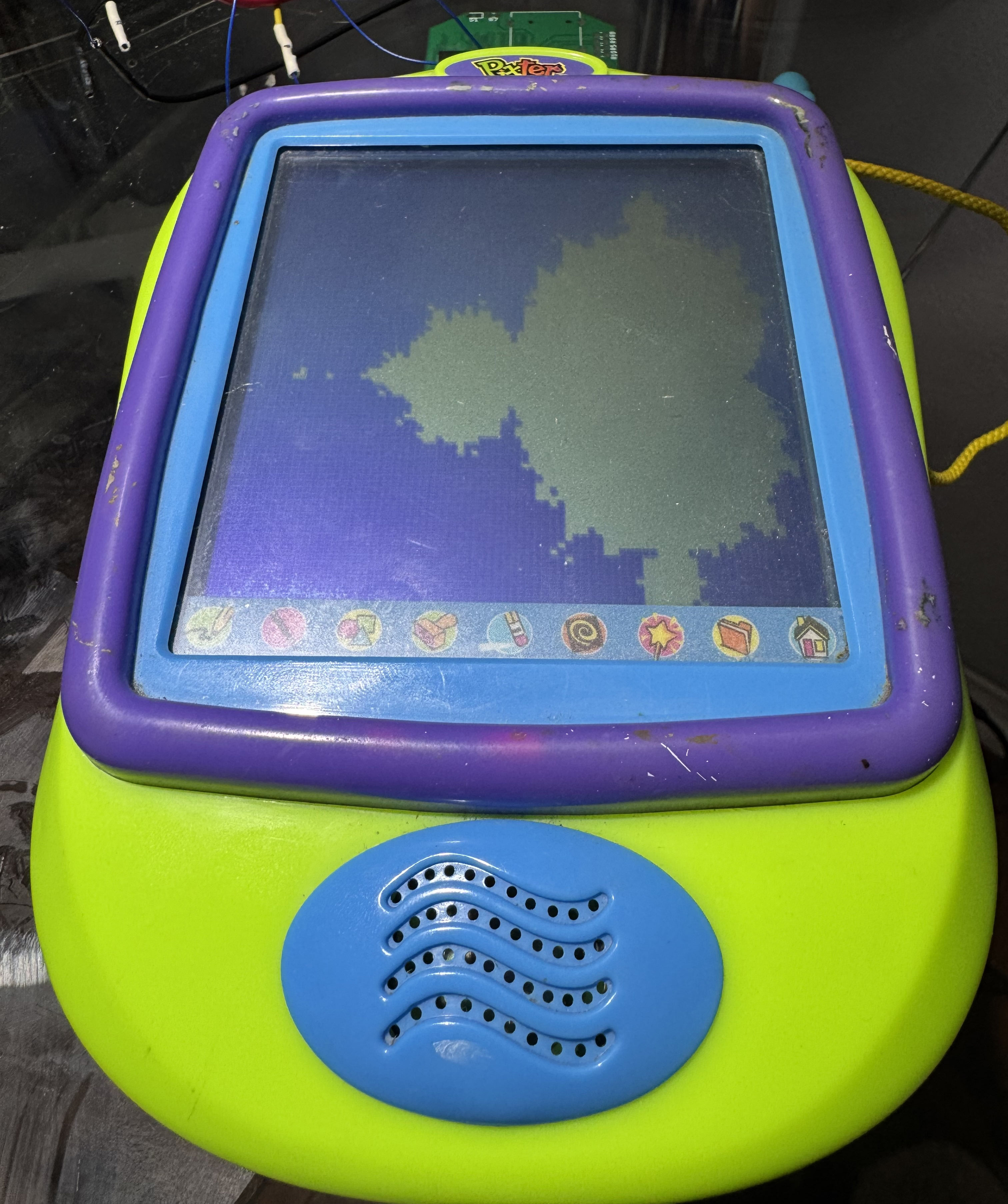
I ported PalmOS to Pixter Color. What cool programming could I do for Pixter Classic? Well, there are no good C compilers for 6502, and I really am quite over writing assembly for 8-bit MCUs, preferring either 32 bit ones or 4-bit ones. I had one cool idea, but it required being able to handle interrupts, and in Pixter's SoC, interrupts always use the vector table at 0xfffa in ROM that I cannot change. Or can I? The manual for GPLB3x mentions that there is a bit one can set to map 0xc000..0xffff to the external BEX bus instead of the internal ROM. This would allow me to take over interrupts! I just need a minimal game-like header to do that, and then the interrupts are mine!
This worked with my Pi Pico 2 based BEX slave emulator, but it did not work with my GPBA01B-based real Pixter Classic carts. Why? Well, GPBA01B is not designed to map that address range, it ignored it, the bus was left floating, and the CPU fetched garbage. Each vector is 2 bytes long, and only one matters - IRQ. What if I added weak pulls to the bus on my cart? Then, when the GPBA01B leaves the bus floating, the Pixter Classic's SoC will read from the bus a value determined principally by those pull resistors. Initially this did not work as I overestimated the output strength of the GPBA01B and my 1KB pull resistors overpowered it. Switching to 100KB pull resistors worked. By necessity, every unmapped address will read as the same byte value. So what byte value would work for me? It needs to map to an address range I control. I chose to pull up DQ5 and pull down all other data lines. This causes the floating bus to read as 0x20, causing the SoC to read the IRQ vector of 0x2020, pointing to memory that IS mapped by the GPBA01B. Awesome!
So what did I program? If you have been following my projects enough, you'll probably guess - I've done this a few times before to underpowered devices. Yup, I wrote a full Cortex-M23 emulator with access to display, PWMs, UART, and even interrupts. It can be flashed on a cart and run. Most of the cart's 1MB of flash is left free for ARM code, and you can even populate a 1MByte SRAM on the cart, with the RAM available to the virtual ARM core, thanks to GPBA01B being able to address multiple memory chips.
This Cortex-M23 emulator is downloadable in source and binary forms on the bottom of this page.
The one weird pin on the cart
There was one pin on the Pixter Classic cart slot whose meaning was still eluding me. Some games toggled it sometimes, some did not touch it. It was always operated as a GPIO. But why? I opened a cart to see where it went. Bewilderingly, it went ... nowhere. There was a SOIC-14 footprint on the board that was unpopulated, and the signal went there. Only there. I opened another cart whose game toggled that pin. Same story! What the hell? Who needs to toggle a pin that goes nowhere. Why? Lacking any better ideas, I traced where other pins of that unpopulated SOIC-14 went. All but one were uninteresting. The interesting one went to "write protect" pin of the NOR flash that is used to save game state. Hm. Maybe the SOIC-14 was some sort of a logic gate, and its purpose was to protect the flash from accidental writes? I checked again when the pin toggled, and indeed it went high before saving and low after saving. I guess the intent was that, but after a while they found the cost of the SOIC-14 logic chip not worth it, but the game logic stayed. Well, toggling an unused pin is harmless, after all.
Resistive Touch Panels on the Cheap
Resistive touch panels come in two major varieties: 4-wire and 5-wire. At least I keep hearing this. In reality, I have literally never ever seen a 5-wire system. Every chip that supports resistive touch panels seems to support both of these systems, and I strongly suspect this is a conspiracy to make me think I am crazy. Has anyone ever really seen a 5-wire resistive touch panel, or is it more that you keep hearing that it exists but never see any evidence? It is like the Loch Ness Touch Panel! Anyways. Pixter's touch panels are all 4-wire like all others I've ever seen. The theory of operation of these is not complex, and I'll walk you through it, since understanding it is key to understanding the insanity of how Pixter Classic makes it work.
Imagine a sheet of plastic, coated with a conductive clear coating. It has moderately high resistance, but it is also quite uniform, which is important. On two opposing sides, make a conductive low-resistance contact. Now imagine a second such sheet, rotated 90 degrees from the first, so that if the first's conductive contacts were on the left and right sides, this one's are on top and bottom. Now, place them on top of each other with a spacer between them around the edges, such that they are not touching. We now have four wires coming out of this sandwich. Imagine that the user uses a stylus to press on the screen somewhere. The top sheet bends and contacts the bottom one at that point. Let us consider all the things we can do with them and all the things we could measure. Say we connect the LEFT pad to +3V, and the RIGHT pad to GROUND. this means that the voltage at the contact point is proportional to how far along the left-right axis the touch is. We use either of the TOP or BOTTOM contacts to measure this value using an ADC -- we have found the X coordinate of the touch. Note that which one we sample with does not matter since the resistance of the sheet is negligible compared to the input resistance of a typical ADC, so the resistance of the TOP-BOTTOM sheet is immaterial to this measurement. Also note that it does not matter whether LEFT was +3V or RIGHT, just as long as we know which one was.
Now, instead, we connect TOP to +3V and bottom to GROUND. We use our ADC to sample LEFT or RIGHT contact. Again, it does not matter which we use. The voltage at contact is now proportional to the position of the touch along the top-bottom axis. We have thus calculated the Y coordinate of the touch. Cool. What would these measurements have produced if there was no touch at all? Most likely -- noise since there would be nothing at all connected to the sampled plate. So then how do we detect if there is a touch or there is not? Well, imagine now that we connect, say, LEFT and RIGHT both to GROUND, we apply a very weak pullup to TOP or BOTTOM, and we sample it. If there is no touch. we'd see a high value since the pull up pulls the plate high and nothing pulls it low. If there is a touch, the value would be low, since the resistance through the plates to GROUND would be lower than our weak pullup. In fact, the stronger the pressure of the stylus (or the larger the contact area), the lower the resistance through the plates and the lower our sampled value. This is usually referred to as a Z-measurement and it can approximate pressure or contact area roughly. But also, it can be used to detect whether there is a touch at all. Note, that you can even use this method to generate a pen-down interrupt without needing to check actively. Just connect the plate to a GPIO and interrupt on the falling edge. Again, note that the same could be done by flipping which plate we drive and which we sample, and the levels could also be inverted (drive the plate to VCC, use a weak pull-down). With some loss of precision on the pressure measurement, you could even only drive one side of the other plate instead of both.
Generally, this is how one drives a 4-wire touch panel (again, the only kind I am 100% sure actually exists, I swear I am not crazy). You set it up for Z-measurement and interrupt on falling edge. When you take the interrupt, you sample X, then you sample Y, then you sample Z. If Z indicates that the pen is still pressed, you process (x, y) as a point through whatever pipeline you have for this data, then you repeat the X, Y, and Z sampling. If, instead, Z-sample tells you that the pen is no longer down, you tell your processing pipeline that the pen is now up, and you re-enable the interrupt and reconfigure your panel for Z-interrupt.
It is notable that while chips exist that do this for you, and many SoCs have special units to do this for you, this is not too hard to do manually either. Let's design a minimal way to do this. You'll note that in most cases each plate needs to be driven to at most one level. So: we'll have a P-FET (call it Q1) to allow us to drive "RIGHT" to VCC, a P-FET (Q2) to allow us to drive "TOP" to VCC, an N-FET (Q3) to drive "LEFT" to GND, an N-FET (Q4) to drive "BOTTOM" to GND, and another P-FET (Q5) in series with a high-value resistor to allow us to drive "RIGHT" to VCC via this resistor. We'll connect "TOP" to ADC input 0, and "RIGHT" to ADC input 1, "RIGHT" also connected to an interrupt pin "INT". This is the minimal manual 4-wire system. FETs are used since they do not have the voltage-drop issue that BJTs do, making the math simpler and more linear. Let's prove that this is complete. Note that an N-FET is turned on when the gate is high, a P-FET is turned on when the gate is low. I will just say "on" to mean "whatever the gate needs for the transistor to open".
- Wait for pen down: Q5 on, Q4 on, "INT" enabled for falling edge. Q4 makes the top-bottom plate ground, Q5 weakly pulls up left-right plate. If there is a touch, "INT" goes low as top-bottom plate overpowers the resistor. If there is no touch, "INT" is high still.
- Z-sample: Q5 on, Q4 on, ADC input 1 sampled. Q4 makes the top-bottom plate ground, Q5 weakly pulls up left-right plate. If there is a touch, ADC value is low as top-bottom plate overpowers the resistor, pressure and touch area determines the contact resistance and how low the ADC value is. If there is no touch, ADC sees a high value as pullup keep the plate potential high.
- Y-sample: Q2 on, Q4 on, ADC input 1 sampled. Q2 and Q4 create the VCC-to-GND gradient on the top-bottom plate, we sample the left-right plate to find Y position.
- X-sample: Q1 on, Q3 on, ADC input 0 sampled. Q1 and Q3 create the VCC-to-GND gradient on the left-right plate, we sample the top-bottom plate to find X position.
Resistive Touch Panels beyond Cheap
Allright, now that you know how one should do this, let me tell you how you should not, by which I mean, let me tell you what Pixter Classic does, because it is both sickening and clever at the same time. First of all, it has no ADCs, so there isn't a way to sample the values. If that was not enough of crotch-punch, in a desire to cut more costs, they decided to save $0.000001 per device and used the cheaper BJTs instead of FETs. This means that instead of the voltage on each plate spanning almost the entire range of VCC-to-GROUND, it now spans a range that depends on the voltage drop of the particular transistors used in this particular device. Even BJTs made on the same production line in the same way can differ quite a bit in their voltage drop, and a difference of 0.1v can be a difference of 10 pixels onscreen - quite big when drawing. Bold choice.
How do you sample an analog voltage without an ADC? Well, you can use a comparator and a DAC. You output a varying voltage and see when the comparator output flips, that is approximately your input voltage. This is a useful hack because comparators (and any op-amp is a comparator if you wish it to be) are cheaper and more available then ADCs. But now you need a DAC. Pixter Classic's SoC does not have one of those either. It does have PWM units, which can be used as a DAC, with some filtering, but they are both used for other purposes and are unavailable. It does have a lot of GPIOs. So... they used the 8 GPIOs of PortA in a R-2R configuration as a shitty low-quality 8-bit DAC. The problem with R-2R DACs is that the more bits of precision you want to get out of them, the more precise resistors you need. For 7-bit precision you already need 1% accurate resistors -- not cheap. For 8-bits as we have here, you need 0.4% accurate resistors -- even more not cheap. And when making the Pixter Classic, Fisher-Price was very much trying to be cheap. So ... they just used cheap +/-5% resistors -- the embodiment of YOLO.
A dual-comparator is used -- one per touch plate. The other inputs are both connected to the R-2R ladder. Binary search is used to "measure", first the input value is compared to 0x80. If input is higher, next guess is 0xc0, else next guess is 0x40. You get the idea. In 8 comparisons, the precise matching value can be found. For some very loose definition of the word "precise". The same is done for the other plate, and for Z-sample. There is no interrupt mode here. Pixter Classic just polls the pen when the current game asks for it.
The manual for the device tells you to calibrate the touch panel as soon as you put in new batteries, and with the per-device variance in the BJTs it makes sense. The calibration is saved in EEPROM and remains good until you choose to recalibrate. But it would be a shitty out-of-box experience if this really was required. Here is where some perverted cleverness happens. There is no normal 4-wire-panel operation mode where you drive the same point as you sample, but Pixter Classic does this. They drive-and-sample both of the points to ground and to VCC and thus can calculate the voltage drop of the transistors in this particular device and can thus approximate a valid-ish calibration out of the box. This is done if the EEPROM calibration area is empty. I have many doubts that the extra engineering hours needed to come up with this cleverness cost less than the savings on the FETs. I suspect Fisher-Price lost money on this tradeoff. But it is a cool hack, and like all cool hacks, it is very nice once you understand it, and infuriating when you are reverse engineering and simply cannot grok why someone would use an ADC to sample the voltage at the collector of an open transistor.
Pixter Plus and Pixter 2.0
After Pixter Classic (which was actually just called "Pixter", but I needed a better name for it and now that you've spent an hour reading my article and are invested, I am sure you'll adopt my nomenclature too), there were two follow-on products. Curiously, while they both are upgrades compared to the Pixter Classic, neither of them is an upgrade on the other. I would have guessed that they came out the same time, and consumers had to choose which feature set they liked more, but that is not how the history played out.
Pixter Plus
Pixter Plus came out a year after Pixter Classic. It featured a very similar physical shape, played the same games using the same cart slot, and had a similar number of those infuriating indescript black blobs on its motherboard. What it did have over the Classic is a hole in its front plate where one could insert a new "lightbulb" attachment, which was literally a tiny incandescent lightbulb on a flexible stalk. Its main purpose was to make your parents buy batteries for your Pixter at twice the normal rate, but it also had the side-effect of allowing you to somewhat see the screen in the dark. The number of built-in activities was also increased to include a few games in addition to drawing activities. Additionally, Pixter Plus has 128-times the storage of Pixter Classic, allowing more than one image to be stored in memory. Another cool feature was that you can customize the power-on animation of your Pixter Plus by picking it out of a large set of options, and adding your name or another text to it. I guess kids do love customizing their things. Some of the extra NOR flash memory is spent on this new functionality. The user interface limits the number of stored images to less than 163, but there is space for 163 images, if one were to pack them optimally. Of course no such packing is done. The memory chip somewhat resembles the SST39SF010A, but is not exactly a perfect match. Of course, the chip is behind an internal BEX, since the SoC still lacks any way to address such a large memory directly.
From a technical standpoint, the SoC is upgraded, now it has 4KB of RAM instead of the 2KB that the Pixter Classic SoC had. This allows for a few more temporary buffers for the software to use, and thus a few more effects are possible, like flood-fill and some image rotations. The cool animations the Pixter does for erasing are also improved, adding a few new ones. The number of melodies in the internal Melody Chip also grew -- while Pixter Classic has just 2, Pixter Plus has 9. Just like Pixter Classic, Pixter Plus runs its SoC at 6MHz, and other than a few changes to which pins do what, it is not much different internally. Dumping the internal Melody Chip was done in much the same way as for Classic.
Pixter 2.0
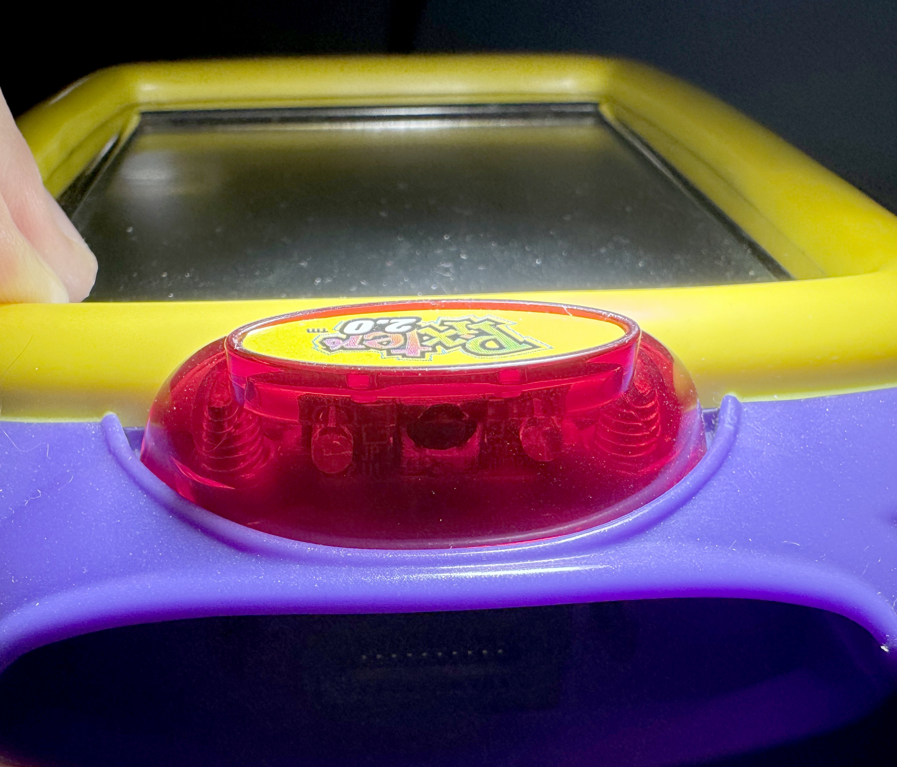
This one came a year after the Plus, and it is not quite a direct upgrade. As before, some pinouts change. The Melody Chip here also has 9 melodies, but they are distinct from the ones that Pixter Plus has. No idea what the thought process on the melody changes was. The RAM amount stays at 4KB, same as 2.0, the CPU is now at a slower frequency of 5.48MHz, and I guess the extra BEX chip and the 128KB of flash were costing too much -- they are gone like they never existed, Nikolai Yezhov would understand. The hole on the front of the device for the flexible light is gone too, but the feature remains, it is just that the hole is now on the side of the device, since the top of the device now has something else....
The marketing copy claimed that Pixter 2.0 has capabilities to "wirelessly exchange images". Normally, the world "wireless" would imply some sort of ISM radio, but this does not fit into the price profile of the Pixter series, which (as is surely evident by now) was always engineered to cost "as little as possible, minus an extra 10 percent for good measure". But, indeed, Pixter 2.0 has ability to send images wirelessly ... on the 320THz band. Yup... They used a cheap infrared LED and a phototransistor+filter package to send images wirelessly, precisely as promised. How did it work? A PWM unit creates a carrier frequency, and a UART unit frames the data. Connect one pin of a LED to one, the other to the other and you get UART-modulated-carrier-modulated IR blinks. On the receiving end, the phototransistor with a frequency filter, like the kind used in TV remote receivers (such common, so cheap, much economies of scale, wow -- I bet Pixter team was happy) receives the signal and detects that it is modulated by the correct carrier frequency. If so, it will be output on a pin and that goes into the UART's RX input. With some luck, this system can work.
Ideally, if you were designing an IR data exchange protocol, you'd want to add some forward error correction and maybe negotiate the data rate to match conditions. But, that would require a lot more engineering effort than the Pixter team was willing to put into this. I guess we should feel lucky that they at least had the decency to use checksums to avoid receiving random noise as images. Now that Pixters could "communicate", they also can be named. In the save/load dialog there is now a button to give your Pixter a name, and when you send someone an image, they will see who it is from. I suppose the Pixter team imagined a world where there are so many kids around with Pixter 2.0 devices that you would not otherwise know who sent you an image, over the enormous range of "12 inches or less".
The VM had a few opcodes added to it for IR sending and receiving. I worked out some of them, but not all, since it was not necessary. There was a way for games to use IR too. There are two more native callouts (at 0xbf12 and 0xbf15). Again, I did not decode it all, just enough to understand what it is and what it is for. There is more to understand here. Another exercise for the reader. Enjoy!
Pixter Pocket
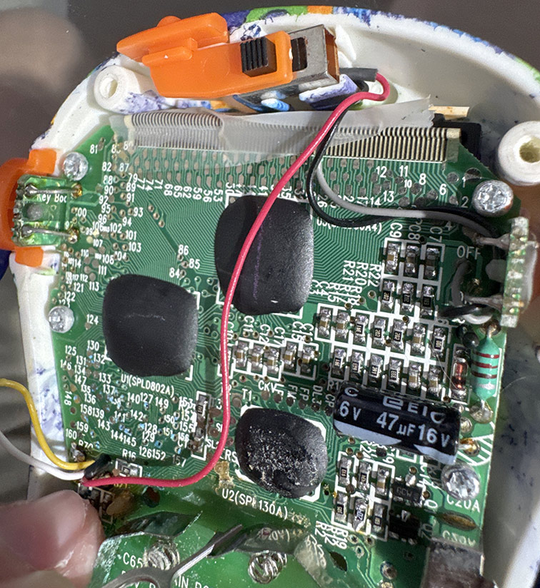
These each had only one game in them, no cart system, and no IR, preventing any sort of arbitrary code execution on them. They were also non-touch-screen, instead having a D-pad and 3 additional buttons for interactivity. After a lot of searching, I did manage to get my hands on one, but the display was broken, which is not unexpected in a cheap product after 20 years. Opening it showed a board with LABELED black blobs! If only I had known, I would have saved myself some guessing. The main SoC is labeled SPL130A, which is definitely not what runs Pixter Classic (too small of a RAM, etc), but it would have given away the family name and that it is a 6502. The other two black blobs are the row and column drivers for the LCD. There is no Melody Chip here - the device only does simple beeps. In any case, nothing more to be done with this device -- it cannot be programmed and without decapping the chip it cannot be dumped. A later though caused me to read up on a few other family members of this chip, and I suspect that Pixter Classic's SoC might be the SPL133A. The way the datasheet talks about the register 0x000e sounds reminiscent of my discoveries with regards to it. But, of course, I am unable to find the "programming guide" for the SPL13x series, and the datasheet lacks detail. If you have a copy of the programming guide, please reach out. I know the good old PUDN website had it, but sadly ... RIP PUDN.
Preservation
File format
Now that I had decided to properly preserve all things Pixter, I had a few decisions to make. First of all, there was no proper file format for Pixter cart dumps, since until now, nobody had figured out how to dump them properly and completely. This meant that I could define my own. What are the things that every file format needs? First of all, it needs a recognizable magic sequence of bytes as early as possible for easy file type detection. Then, it needs ability to store a file version for future extensibility. Additionally, it should be little-endian since approximately all modern desktop machines are such. Finally, it needs extensibility to represent all types of the thing it proports to store. What does a file format NOT need? Hard-to-parse-in-C nonsense like XML or ZIP. Well, OK, on with my format...
The first 15 bytes of the file are the magic sequence. It is the ASCII string PIXTER CLASSIC! for a dump of a Pixter Classic cart, PIXTER COLOR!!! for a dump of a Pixter Color cart, and PIXTER MULTI!!! for a dump of a Pixter Multimedia cart. Next comes a byte that versions the file format. Currently it must be precisely 0x01. Then comes a 32-bit value representing the number of Melody Chip melodies in this dump. Then come that many 32-bit offsets (from file start). If an offset is zero then this melody does not exist (the list of melodies need not be dense). Each melody runs until the start of the next thing in the file (next melody, code, or file end). Afther these melody offsets come three more offsets. The first is for "code 0", the second is for "code 1", and the third is for file end. If the file is valid, the very first nonzero offset should point to just past all of these offsets, and the very last offset will be equal to file length.
Melodies are stored as unsigned 8-bit samples at 22,050Hz, mono -- trivial to play. Now, what is "code 0" and "code 1"? For Pixter Color and Pixter Multimedia, there is no "code 1". There, "code 0" contains the complete dump of the cart's ROM. For Pixter Classic, "code 0" is the dump of the entire cart ROM, "code 1" is the dump of the area that the cart presents in the address range 0x2000..0x3fff. Since technically, there is no requirement that this memory area be present in the main ROM, it is dumped separately as well, for proper emulation.
I use the same file format to dump the consoles' ROMs themselves. You can grab all the console ROMs here. I did not host the cart ROMs on my site, my tiny little VPS will not handle it, so grab your bittorent client and click the magnet link. You can also find everything on the Internet Archive: here
Emulating Pixter Color
What good are dumped carts, even if in a fancy new format, if there is no emulator to use them? Well, I suppose you could make more carts, and indeed I did demonstrate that, at least for the game ROMs. I do not know how to replicate the Melody Chips, but I did program an RP2350 to act as one successfully, playing the 22,050Hz samples from an SD card. Still this is not of much use, since Pixters themselves will, over time, become rare. And how will the world go on without the masterpiece that is "Barbie Fashion Show"?! No, this would not do!
How hard could it be to emulate?
Pixter Color, being an ARM device, and the one I had encountered and understood first, was the first to be emulated. I based it on my previous work emulating ARM SoCs for PalmOS 5 devices - uARM. I added support for LH75411, and its various hardware blocks. The built-in ROM booted relatively easily. Getting the touchscreen to work was not easy, though. Pixter ROM's touch code was very touchy about how fast the ADC unit should become busy and how fast it should complete measurements. It took a lot of annoying evenings and a lot of swear words to get it to work. But once it worked, it was glorious! Along the way I learned a bit more Pixter Color history. At boot, a GPIO (PE6) is read. Based on this, the clocking and various timeouts are set. Evidently they considered using a 17.7456MHz crystal in the Pixter Color, and setting that pin high changes all timers and such to make that work. Setting it low sets timers for 18MHz, which is what the Pixter Color final boards have. The one and only button on the Pixter Color (the pinhole "calibrate" button on the back) is mapped to the ENTER key in my emulator.
I spent a lot of time puzzling out how the contrast adjustment that was possible on the Pixter Color via the "save/load image" dialog worked. There was a slider there and it affected the real screen contrast. On an STN screen, such a thing is accomplished by varying an analog voltage provided to the screen. I did not know which VM opcodes were used to do this (yet), and had no way to find easily. I did want to figure it out though. I guessed that it is likely a special opcode. So I added code to uARM to log every opcode run by the VM and build a histogram. Then I ran the emulator a while. I then did the same but also dragged that slider a lot. I then compared the histograms, looking for opcodes that were not in one but present a lot in the other. After some cleanup of the data, I found the SETCONTRAST opcode, and was able to trace where it goes and what it does. It seems that the lower 4 bits of GPIO port H are used to set it. They always output low and their direction setting is what is changed (they are externally pulled up). Trying this on a real Pixter Color proved the theory correct. I also added this to my PalmOS build, which could then also adjust the screen contrast! I did not bother emulating contrast adjustment in the emulator though, since I do not emulate the depressing realities of the display itself. There is no way to emulate the poor viewing angles, the shitty color reproduction, and the questionably-present-at-all contrast of a bottom-of-the-quality-and-price-barrel STN display such as the one in the Pixter Color. You need to experience it yourself! Accept no substitutes!
Saving images is hard
There is flash memory inside the Pixter Color for saving your drawings. It is a normal-ish NOR flash chip that mostly follows JEDEC standard commands, though it differs from the JEDEC spec in how it shows itself to be busy during writes and erases. I deduced the behaviour from disassembly, and confirmed by running my own code on the device. During write or erase it will read as a byte with the top bit clear. Once done, it will read ONCE as a byte with top bit set, after which it will return to read mode and the reads will return actual data at the read address.
Of course, things were never going to be that simple! If you recall from the LH75411 user guide (you DID read the 515-page user guide I linked to, right??), the chip only has 4 external chip select signals. That means (to an approximation) that it can address 4 external memory chips. The first is the internal ROM. The second is the on-board RAM. The third and fourth are wired to the cart slot. So that leaves us with ... zero chip selects still free. I counted them. Twice. So now we need to connect this flash to the SoC. Well, one option is to simply bit-bang it. It is 128KB in size, 8 bits wide. So this would use: 17 address wires, 8 data wires, and 3 control wires (chip select, write enable, read enable). 17 + 3 + 8 = shit ton (that is a shitload in metric, for my european friends)! We cannot just throw GPIOs around like that. We'll run out too fast. So what to do? Well, when all you have is a hammer, every problem looks like a nail. And when in all your previous devices you used the BEX bus, well, I imagine it starts looking pretty attractive as a solution to any problem. Luckily, in this case, it is not an absolutely terrible solution. BEX only needs 10 wires, and can address this NOR flash chip well. Pixter Color does precisely this. It has a BEX bus that has a BEX expander on it which has this 128KB flash behind it. Perverted? Yes? Slow? Also yes!
I wrote an emulator for a BEX expander, wired up an emulated flash behind it, and after some tweaking and tuning, my emulated Pixter was able to save drawings and load them again from virtual NOR flash. I went to take a shower soon after to wash all of ... this... off of me!
Making game carts work
The emulator would not initially even try to detect external carts, even when I attached them to the proper address. It took a little while to find that GPIO PG6 (connector pin 46) had to be high for Pixter to even try. It also checked this pin before every VM instruction. My guess is that this allows detection of cart removal while playing the game. Well, I emulated the pin to be high and it started trying to read the cart.
Adding support for external carts with games took only a little more work after that, since they are just another ROM at 0x48000000. Just as I was done congratulating myself on how easy this was, how well it worked, and what a genius I was, I noted that some games failed to save progress. Hmm... Well, it makes sense that the in-Pixter NOR flash is not used to save game state. True, it can be used to store an image in one game, and load it in another, but this is merely for one image. Game-specific state by definition differs per game, and there is no sane way for them (and all future not-yet-written-at-the-time) games to share the same space. It is after all, not a filesystem, but just a NOR flash. OK. Most games (like Arcade) do not need memory at all. Some do. How was this handled? Hm, this might explain why some carts had another tiny chip inside. It as not labeled, but after some more disassembly, some probing, and some ripping-out-of-hair, it became clear. They use an i2c EEPROM inside the cart to save game state. A fine solution indeed. However, LH75411, being a minimally-featured-at-best chip, which would have omitted the ALU, had the ARM spec allowed it, has no i2c unit. This is no disaster - i2c can be bit banged, and indeed this is what most Pixter Color games that wish to save state do. GPIO D2 is used as SDA, D1 is used as SCL. They are available on the cart connector and, I guess, this use does not conflict with their other potential uses. Figuring this out was 90% of the work. Emulating a bit-banged i2c EEPROM correctly enough to fool the bit-banging code in the games was the other 90% of the work. In any case, it worked...eventually
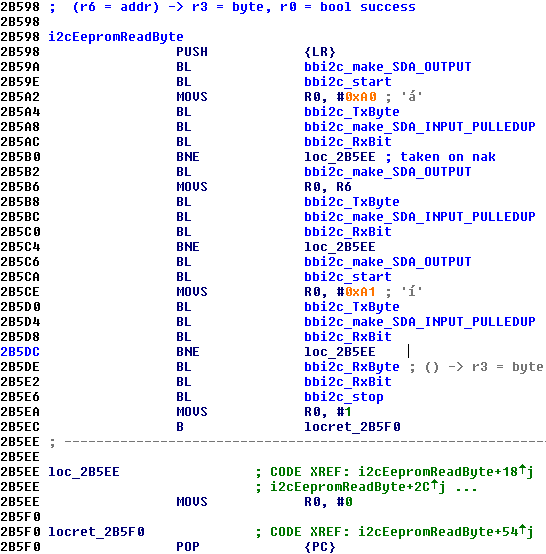
There were i2c bugs in their bit-banging code. I did not realize this right away, so I spent a lot of time sorting out why my i2c EEPROM emulator was misbehaving. Turns out it was not, their bit-banging code was. It works in the real world due to luck - real EEPROM chips ignore shorter-than-a-byte transmissions, and they can live without a STOP at all, since every START will just become a RESTART and that is weird but likely OK. Here I show you the code that is used to read from an EEPROM. Do you see the issue? Yup... SDA is not made to be an output before signaling STOP, and thus SDA stays high the entire time and no STOP is signaled. I verified this on a real device as well. It is just lucky that their chosen i2c EEPROM - 24C02 is to tolerant of their carelessness. As an extra aside, you'll note that no semblance of ABI is respected in this code. It is not customary in ARM to return status in the Z flag, and yet here we are...
It is also notable that the i2c bit-banging was done in native code by every cart. So how can it work on Pixter Multimedia, where the SoC differs and so does the cart pinout? This was considered. The native callouts use opcode NATIVE_CALLOUT_2C, with selectors 0x06..0x07. Pixter Multimedia's VM, when it sees those selectors used does not call native code in the cart, instead doing the work itself using the proper pins. Thus it is evident that Fisher-Price allocated these numbers in some orderly fashion, to allow this future-proofing. Actually, not bad!
Audio is hard
I wanted audio to work as well. I did not spend weeks reverse engineering those Melody Chips, and more weeks dumping those melodies out of them only to have that all go to waste! In all my previous years of writing emulators, I had never bothered emulating audio fully. Usually I'd only take it far enough to make the emulated SoC happy. This generally means emulating the DMA to get the data from the buffers, and firing properly-timed interrupts on the status of the transfers. Playing actual audio out the host speakers was always something I did not bother with. Mainly, this is because I do not like noise, but also (in no small part) this is because audio is a pain in the ass and I am lazy. You see, the basic primitive of audio playback in modern OSs is not "output this PCM value, until I give you another", while at the emulator's level that is what you'd ideally want. This desire is redoubled when your audio output is fake, like Pixter's. There is no internal DMA unit reading a series of samples from RAM. It is literally code setting PWM registers whenever it wants. No fixed sample rate, no nothing! Stick that into your audio API and see what comes out! OK, fine, in actuality while there is code in the ROM to play back audio at sampling rates not equal to 8KHz, I have found no evidence of that code path ever being used.
Well, I decided to grit my teeth and once and for all figure out how to emit audio using SDL2 (my preferred UI toolkit). Imagine my surprise and elation when I learned that SDL2 indeed has a "output this PCM value, until I give you another" API! The name is less prosaic, of course, but I guess you can never really get ALL that you want. The API is SDL_QueueAudio. Now, queueing one sample at a time is very much NOT performant, efficient, or even sane. But my goal was not to produce an emulator that can be described with any of those adjectives. I am very much producing a reference on how Pixter works and how to emulate it. Someone else, who is more tolerant of audio headaches and emulator frameworks can take this info and spin up a nice MAME module for it. Maybe even you, my dear reader?
In any case, on a fast-enough machine, audio output worked and sound effects in games started playing the proper sounds. Very cool! Melody Chip output does not go via the PWM units, however, it is produced by the Melody Chips directly and mixed into the audio amplifier inputs. Luckily, SDL lets us open multiple output streams and can mix them for us. SDL2, I love you! I wrote an emulator for the Pixter Color Melody Chip, hooked it up to the proper GPIOs for the in-cart Melody Chip (D0 = clock, D1 = data, F6 = isPlaying). Instantiated another one for the in-Pixter one, hooked that up to the other emulated GPIOs -- the ones that are meant for that (F0 = clock, F2 = data, F1 = isPlaying). It worked ... right away, for once! Games now looked and sounded like they did on the real device. At least they did on my fast MacBook, YM*W*V.
That cursed adapter
I knew that emulating Pixter Classic games running on the Pixter Color through the adapter, like the real device can, would be a pain. The whole situation just had that feel of "I know they hacked it together in some terrible way to make it work, it worked, and they never dared to touch it again" that all legacy compatibility situations have. I was not wrong. As you'll recall, Pixter Classic carts expose the BEX bus and a "isPlaying" pin for the Melody Chip. Elsewhere in this increasingly-booklike-article, I noted the pinout of the Classic-to-Color adapter. The BEX bus is all GPIOs to the LH75411. Golly, just what I wanted, more code to write for watching an emulated CPU toggle GPIOs and then trying to decode what it meant or implied by that! One curiosity here that I did not expect was that the internal BEX bus used for the savegame NOR is the same one as the external one used to talk to Classic Carts. They used the chaining ability of the BEX chips to do this. I would probably have appreciated the cleverness of this approach a lot more if it had not taken me so long to finally figure it out. Games started working once I debugged away all the bugs in my GPIO-to-BEX adapter code.
Luckily, Pixter Classic games did not bit-bang any i2c on any GPIOs for their state savings -- the Classic connector had too few pins for that. So instead they included a NOR flash in the cart and wrote to it ... also through the BEX chip. All the carts I opened (a very destructive process, which at this point in time I admit I was beginning to enjoy) used AT29LV010 for this purpose. Seeing an actual labeled chip and not a blob of black epoxy was euphoric, believe me. At this point in time I had had a lifetime's fill of black blobs on green board with no labels! Emulating AT29LV010 was not hard, and Pixter Classic games that saved state started working too!
With some investigation, it was able to find the analog input that the battery voltage goes into for low battery detection (AN8), as well as the divider ratio used (0.24). I then wired up a virtual always-full battery there. You're welcome. The volume knob on the side of the device was also an interesting thing. Now, you would expect that to be an input into the audio amp to set the gain somehow, right? Or simply used to scale audio amp's inputs. NOPE! It is an analog input into the SoC's ADC. The software occasionally samples it and multiplies the output samples by the value. Why? Honestly, I am at a loss for words, this saves no cost, saves no software complexity, and really accomplishes nothing at all. But oh well. The emulated device always sees that knob as being set to maximum volume. I dare say that the Pixter Color emulator was getting close to complete, or at least as close to complete as I cared to make it.
Emulating Pixter Multimedia
This was not a hard task given that Pixter Color was already done. The SoCs are similar, so the main additions were buttons (trivial), a new I2S peripheral in the SoC, and the new DAC. The gods had taken mercy on me, and the DAC was not a black blob, but a nicely laser-labeled TLV320DAC26. It uses I2S for audio data transport and SPI for configuration. The LH79524 has one peripheral that can do SPI. They call it the SSP. Buuuut... it is also the only peripheral that can do I2S. And it supports DMA making audio much saner. So they, predictably, use the SSP to send I2S data to the DAC. The configuration SPI, in a continuation of their tradition of bit-banging everything, is bit banged. The pin usage for this SPI "bus" is M4 = nCS, A6 = MOSI, H2 = MISO, and A7 = CLK. As for the buttons, the "calibrate" button is still mapped to ENTER. Arrow keys map to arrow keys, and "A" and "B" map to .. "A" and "B".
The analog bits are not too complex here either. The ADC/touch controller is similar to the one in LH75411. The battery measurement is multiplied by 0.27 and is applied to AN9 analog input. The volume knob is still merely an analog input as well, it goes to AN4. Curiously, pin 46 on the connector is not polled here. Pixter Multimedia's VM seems to not at all care if the cart is inserted, nor if it is yanked out during play. Curious, but irrelevant in the grand scheme of things.
The new NAND-style carts that are unique to Pixter Multimedia are supported by using the data bus's low 8 bits for data and nWE, nOE, and nCS for control. Basically, they just configure the external ROM interface as x8 and it magically works. NAND needs two more signals actually: CLE and ALE. Cleverer designers than what Fisher-Price could afford usually connect those two signals to some of the higher address bits, and thus all NAND interface becomes writes to one of 3 addresses and reads from one. These guys did not think of that, so instead GPIOs are used. B6 is CLE, B7 is ALE. The "ready" signal is on B1. It is important that the NAND bus idle high and so does the "ready" signal, else the early init code in the Pixter Multimedia ROM will hang. It waits for NAND to be not busy and then issues a ReadID command. If it gets a reply that is not 0xFFFF, it assumes a NAND game is inserted and goes down that path. Else, the previous logic of detecting a Pixter Classic game in an adapter or a Pixter Color game ROM is used.
Despite having a real DAC and DMA to feed it, Pixter Multimedia still has an internal Melody Chip, as I had mentioned. My guess is this was due to institutional inertia, since there is no other sane reason to do this. The game writers, evidently, did get the memo, and all of the NAND-based games that target Pixter Multimedia directly do not have Melody Chips.
Another curious thing that changed is that the shared BEX bus with chained BEX chips is gone. I guess that the BGA package had enough pins to not need this. There is an internal BEX bus used to talk only to the savegame NOR flash, and an external one used to talk to the Classic Cart through the adapter. Why they did not just instead bit-bang the NOR interface directly using those very same extra pins, I do not know. It would have been simpler, faster, and more elegant.
Of course with the switch to the new SoC generation and from a TQFP to a BGA package, the pin assignments for many things changed. The internal BEX bus uses I0..I7 as the data pins, H0 as MC0, H1 as MC1. Very straight forward. The external BEX bus uses A4 as MC0, A5 as MC1, and the data lanes, in LSB to MSB order are: A3, B7, B6, B0, B1, C4, C5, C6. Do not even ask.
Emulating Pixter Classic
This, I did expect to take some time, mostly since I was starting from scratch and not from a ready-built scaffolding of uARM. The initial bits did not actually take long, after all, a complete 6502 emulator in C is just 300 lines on a good day. The periphery of it all took longer. Luckily, I already understood BEX and the datasheet for the GPLB3X, while not being perfectly accurate for Pixter's chip, did help a bit. A lot of experimentation was done on the Pixter Classic itself to help me understand registers that did not match GPLB3X. Once I was able to run native code, I spent a lot of time trying things. This is how I figured out the RAM size, the display configuration registers, and GPIO mappings. I also verified that the chip acts like it has a UART, and self-test code even uses it, but no external trace exposes the UART output signals, implying that likely those pads are not wire-bonded to anywhere. Sad. The one button, same as in Pixter Color -- "calibrate", was wired to the GPIO port bit that it needed to go to.
Of course, the Sunplus 6502 has no i2c interface hardware, so the i2c bus is bit-banged. As before, this is just a tedious exercise of watching GPIOs twiddle and extracting intended meanings out of that. Tedious but not challenging. It took me a while to come to terms that the i2c EEPROM used to store user-drawn images across power cycles was not what it appeared. This chip would respond to four sequential i2c addresses and present a different 256-byte memory array to each. I guess this chip was easier to buy in bulk than a normal garden-variety 2KB EEPROM that does not have split personality issues? Once I understood this, some searching told me that this is likely some clone of 24C08-style EEPROMs, which popularized this sort of perversion.
As mentioned earlier, Some Pixter Classic Carts used an AT29LV010 NOR to save state, and I ported my AT29LV010 emulator code from uARM to here in a few minutes. The shape of the code necessarily changed since in this emulator I let each addressed thing deal with BEX-chip mapping, while in uARM I made a separate BEX module. It did not work right away. Instead I saw jumps to outside of the normal cart ROM map range of 0x4000..0xbfff. I went back to GPBA01B docs, and realized what the 0x2000..0x3fff map is for. Do you see it? It always maps to the first chip select! Even if the current page selects another chip. So when you need to write the NOR flash in the cart, you must select it, thus deselecting the cart's ROM. But then how do you run code to do the write? You could copy it to RAM, but there isn't much RAM. That second window that always maps to the ROM helps here! Adding support for that to the emulator fixed the issue. Story Composer correctly saved and loaded saved stories now. Imagine all the fun you could now have playing it in it 80x80 monochrome glory! I went back and added this to Pixter Color's BEX emulator too, as the same need applied there.
Melody Chip support was more or less the same as in the Pixter Color emulator, as was the general audio support. Again, it was just a matter of seeing the values written to the PWM units and giving those values to SDL_QueueAudio. This got me far enough to see the boot screen, hear the boot jingle, and hear the main menu melody. Touch did not yet work. I did not yet know that it would be more than a week before I would unravel how it was meant to work and emulate it properly.
I described earlier in this page the details of how it works so I will not repeat myself. Let us just say that there were five or six times along the way when I felt like "oh, NOW I get it" only to implement the thing that I "now got" and find that it still did not work. Of course, I could have cheated -- detected that the Pixter ROM is reading pen, and just fake the proper values, but what fun would that be? Instead, my emulator actually emulates the comparator correctly by calculating one input based on the R-2R GPIOs and the other side based on a model of a touch panel and the pen location. This level of emulation detail is unnecessary, but I can be forgiven for having a bit of fun. The practical upshot is that it works, it self-calibrates, manually calibrates, and it is pixel-accurate. I did *not* emulate the 5% resistors' inaccuracy, though.
After 26 years, there is now a fully functional Pixter Classic emulator -- uPixter!
Emulating Pixter 2.0 and Pixter Plus
Not terribly much to say here, actually, since they are quite similar to Pixter Classic. My emulator can be built to emulate either of them and faithfully does that. I really wanted to make sure I understood the IR comms correctly, and what better way to do it than to emulate them? So, if you launch two copies of uPixter with Pixter 2.0 ROMs on the same machine, they will be able to beam images to each other. I did not want to make a UI to configure it, nor add any command line options for it, so, whenever uPixter starts in Pixter 2.0 mode, it will try to listen on UDP port 19180. If it succeeds, it will consider any bytes received as IR data and will send replies by UDP to port 19181. If it fails to listen on 19180, it will listen on 19181 and reply to 19180. Thus two virtual Pixters can beam images to each other. Was this not what you were waiting for your whole life? Ability to draw tiny 80x80 monochrome images in one tiny window, to then send them to another tiny window, as both play the same background melody slightly out of sync with each other? Imagine the hours of fun that could be had!
In all seriousness though, same as with uARM's emulation of Pixter Color and Pixter Multimedia, uPixter is meant more as a reference on how Pixer device work and how to emulate them. I did not seek (and actively continue to NOT seek) to write a full featured and well-UIed emulator. It works, now someone with more forte for writing proper MAME modules can take the info and run with it. Bug you favourite MAME developers and maybe soon you'll have better Pixter emulation options than my barebones emulators
Some final challenges
Emulator development and cart dumping were actually parallel processes, since it took some time and effort to track down all the games. This means that there were many points in time when I thought I was done, only to find yet something else that did not quite work. So it came to be that two games refused to play all their melodies when asked by my melody dumping tools. There was one Pixter Classic game "Music Studio" and a Pixter Color game "Symphony Painter". Both are music related, both have quite a rich set of sounds -- much more so than regular games. A coincidence? I think NOT!
Music Studio
I tackled "Music Studio" first. It played some melodies, but clearly not all since it failed to play a lot of sounds in emulation. I traced the bus and saw that it sometimes asked the Melody Chip to play Melody 0x3c, but no such melody existed. And indeed when it did that, no playback occurred, but then the Melody Chip control bus got weird, with strangely long commands. I simply could not understand what was going on from merely watching the bus. I had to understand the game logic. But, it was written in the weird PixterClassicVM language, for which there was no disassembler. Was... I wrote a disassembler for PixterClassicVM, and you can download it at the bottom of this article. I also wrote one for PixterColorVM, sensing that it would become needed too.
The disassembled code cleared things up a little bit. It seems that to make this very musical game work, they made a custom Melody Chip. It works like a normal one, until it gets asked to play Melody ID 0x3c. Then it switches modes. Lacking any text to draw upon, I simply called this "advanced" mode. The volume requested from the 0x3c command is saved and used for all future playback. From this point on, commands are no longer 9 bits long, as normal commands are. Normal commands are ignored in this mode. Commands are now 24 bits long. Those are logically split into four groups of 6 bits. There is no "loop" mode bit here, and, as I mentioned, no volume setting per-command. Anytime a new advanced command arrives, up to four sounds are played at once. They are mixed together, and the volume scaled by dividing by their number. This avoids overflow when mixing, I guess. The "isActive" bit out of the chip stays active until all four instrument sounds have finished. If some are shorter than others, the longest one determines play time. Of course, a new command can interrupt playback. Sending an advanced command made of precisely 4 requests to play instrument 0x3c exits advanced mode. The precise value of that command is 0xf3cf3c, if you're curious.
You'll note that there are no actual musical notes at play here. The only thing this new mode gives is ability to play a few of a collection of approximately 60 musical-instrument-like sounds concurrently. It is not a fully controllable synth. Still, much more advanced than the usual "play this pre-canned melody" of most games. Now that I understood how to command this chip to give up its secrets, I captured each of the 60-ish samples separately. How to represent this in my file format? How to signal to the emulator that a cart does this? I decided on a simple solution. As all normal carts have at most 63 melodies, melody indices above that are never used. A game that uses such "advanced" Melody Chip stores each of the "advanced" samples at indices starting at 0x100. Recall that the chip also had basic normal melodies, and they occupy normal indices starting at zero.
The emulators (both Classic and Color emulators can play Classic games, so the code has to be in both) detect that a game dump has melodies with indices in the 0x100..0x13b range and emulate an advanced Melody Chip. I found no other games using such a chip, and this actually made me sit down and think some more about the Melody Chips in general. This custom kind of chip further makes it likely that none of the Melody Chips are a stock item. More and more I believed that they are some sort of a Sunplus MCU as well, focused on reproducing music using canned samples and basic math. Sunplus even had such demos in the past. We'll never know, unfortunately, unless someone from Fisher-Price who worked on the Pixter wants to chime in? Or....unless someone decaps and photographs the chip. Want to do that? Let me know!
Symphony Painter
OK, I admit that this one kicked my ass for a few days before I made any useful progress. My previous code that understood the Melody Chip interface was easily able to adapt to the "advanced" Melody Chip of "Music Studio"'s longer 24-bit commands. But here, it was seeing nonsensical variable-length commands, and that is not all. Generally when I write emulators, I will write my code to test any assumption I had made, and to fail very visibly if one is violated. One of the Melody Chip protocol assumptions was that DATA is captured on the rising edge of CLOCK. it has no business changing between there and the falling edge. None at all, but here it was, doing precisely that, causing my emulator to throw up its metaphorical arms and self-destruct. This led me to the solution, eventually...
Some disassembly and brain-against-the-wall-beating later I concluded that indeed this was intentional The data transfer here was DDR - both edges of the clock signal were used. Also, it was much faster that the normal or the advanced Melody Chips, which took 16ms per bit (62bits per second effective rate). The clock for this Melody Chip, which I had started calling MelodyChipXL ran at 1.72KHz - 28x faster. As before, there was a start pulse on the DATA line, but this time it was shorter too. It was only 305us of high state and the same of low. Then the data came, captured both on the rising and the falling edges of the clock. A LOT of data! Each command was 72 bits in length! Thanks to the faster data rate and the DDR transmission, however, it only took 1/7 the time of a normal Melody Chip command. It was not obvious to me at the time why there was a need for such drastically increased data rate.
Having understood the basic structure of the physical layer, I taught my emulator to capture the proper commands, and I also spent some time playing the game on a real Pixter Color, capturing the commands and the produced audio. In fact I think that a few hours of play and capture was required to refute or verify the various theories I had had. Eventually, I was able to convince myself of what was going on. This chip is the REAL deal! It can play up to 8 notes concurrently using a selection of a dozens of instruments, and it can play different notes in each instrument. This is basically a mini-synth! It was not until I had it play me "Yankee Doodle" under my command in a bugle voice that I convinced myself that I was correct. But I was!
If this was not enough, this chip also had two modes. In one mode, it acted a normal Melody Chip, where it plays long melodies automatically, outputs "isPlaying" signal, and acts mundane in all other ways. Even in this mode, it only accepts commands in the DDR 72-bit format, thus distinguishing it from the "advanced" chip discussed before, whose modes included different comms protocols. It can be switched into the MIDI mode where it plays musical notes on various instruments using a special command. It can be switched out of the MIDI mode too, of course. In the MIDI mode, the "isPlaying" signal instead is used for synchronization and toggles every "time unit" of music played. What is a time unit? It is the length of a 1/16th note. Other note lengths possible are 1/8, 1/4, 1/2, and full notes. But how long is a 1/16th note? That can also be varied. Like I said - it is quite fancy!
The structure of the command is pretty straightforward (easy to say now that I understand it). The 72-bit command is made of 8 pieces, each 9 bits long. Each describes a note to play, an instrument to use, and the note duration. The first slot is also special in that it may contain commands. Anything command-like in any other slot is ignored. The parsing of the command slot is also quite strange. I'll describe it in detail. If it sounds weird reading this, believe me, it sounded even weirder sorting it out. And if along the way you say "there is no way someone designed this like this, surely you got it wrong?" Well, I tested everything I write here and verified it. Why it was done this way, I do not know however. I know of no sane person who'd do this.
First, the chip considers the top 6 bits of the command -- a command with the top 6 bits set to all ones, will switch modes. If the lower 3 bits are zeroes (command 0x1f8), the chip will switch into normal Melody Chip mode. Any nonzero value in the lower 3 bits switches into MIDI mode.
In melody mode, only the first piece is used, all others are zeroes. The top 6 bits are the MelodyID to play, and the bottom 3 are settings. 0b001 = play in a lop, 0b111 = stop playback right now, any other value will be treated as "play once"
In MIDI mode, the lower 3 bits are considered first. If they are 0b111, then this is a speed-change command. The upper 6 bits are the new speed. While 6 bits can represent a lot of values, only values 0..6 are used. I tested others as well, though. They all produce unique speeds, but I suspect that after index 5, the chip is just reading garbage past the end of its "speed table". That explains the index 6 being out of range. And indeed in the game, the speed slider does cause a slightly slower playback at speed 6 than 5. A bona-fide bug! The folowing table shows the duration of one "time unit" for each speed setting I bothered testing. Values were captured 8 times and averaged. Note that the Melody Chip has no precise oscillator nor is there a clock input, so the base timekeeping is likely an RC-oscillator which drifts with supply voltage, temperature, and the phase of the moon.
Assuming that speed "6" is an error, the other numbers look round enough. Assuming further that 246ms was meant to be 250ms, and assuming common music BPM values, we can theorize that speed 0 is 60BPM and speed 5 is 120BPM. the others line up (ish) to be 80, 90, 100, 110.
If the last 3 bits of the command are 0b110 instead, this command assigns an instrument for each channel of the 8 that there are. The top 6 bits from each channel's data piece are the instrument ID to use. Nonexistent instruments are silent, and due to the encoding, at most 63 instruments are possible. Only 40 actually exist. I am not a musician so I did not attempt to identify instruments by sounds. You can download the PCI file, split out the sounds, and go wild doing that.
If the last 3 bits of the command are 0b101, this command causes all notes currently playing to stop right now!
If none of the above conditions are matched, then the packet of data is a note for each channel to play. The top 6 bits are the note, with zero meaning "none". The bottom 3 bits are the note duration, where zero means "one time unit" aka 1/16th note, 1 means "two time units", aka 1/8th note, and so on till 4, which represents a full note, 16 time units in length. Values between 5 and 7 produce nonsensical lengths, again, I assume we simply are causing the chip to read past its internal "note length table". I measured them nonetheless. A duration request of 5 produces a note of 188 time units, a duration request of 6 produces a note of 141 time units, and a duration request of 7 produces a note of 2 time units. Note that durations of 5, 6, and 7 are only possible on channels 1..7, on channel 0 they will be treated as commands and cause the behaviours I described earlier instead.
To allow for some jitter in Pixter code, the next note to be played in any channel can be loaded in advance, but only during the very last time unit of the current note. Any notes loaded before this time are simply ignored. If no note is queued when the current note ends, the current note will keep playing for 15 more time units, but if no notes are queued for any channels, the "isPlaying" sync signal stops toggling every time unit. It can be thought to toggle only if a scheduled note or a piece thereof was played.
WOW, so how to capture all of this correctly and how to emulate this? It might be tempting to say that capturing one note of each instrument is enough, and it can be then resampled to play various notes, since the only difference between notes is the frequency, right? Not even remotely! Every key on the piano produces a different-pitched sound, but they all die down at the same rate. If we captured a low key and played it 2x to move it up an octave, it would also die down 2x as fast, which is wrong. Speed of playback, however, should not affect this, but will affect note lengths themselves. Proper synths store a waveform per-instrument as well as an envelope (a volume-per-time table basically). I was NOT going to attempt to reverse engineer how this black blob of a chip synthesized its instrument sounds. There are only 63 possible instruments, and 63 possible notes for each. Why not simply capture each one. This completely eliminates any guesswork and allows emulating this chip across all possible inputs. But how long should each capture be? Well, the longest possible time unit that is not a glitch is 246.423ms. The longest possible note is 16 time units long, and if no command is sent in time, it will play for 15 time units longer. Thus the longest possible duration needed is 7.6 seconds. How much data would that be exactly? 7.6 sec * 63 instruments * 63 notes * 22050 bytes/sec = 634MB. Ooof! However, while the 15 time units of playback past deadline is a verifiable fact, I never saw the game use it, so I decided that capturing 6 seconds per instrument-note is enough (500MB), so I did that. So sue me!
The normal melodies were also captured. How is THIS stored in the PCI file? Well, the idea is the same as for "advanced" Melody Chips. The base index is now 0x200, while the non-instrument melodies are stored, again, at index 0 and on. To make math easier, each instrument is allocated 64 slots, so the Nth note of the Mth instrument is always index 0x200 + 64 * M + N melody in the PCI file. The logic to implement the MelodyChipXL was quite complex, but after all this, the game worked perfectly, which is awesome!
Same as before, I found no other carts using such a Melody Chip, and with how fancy this one is, and how it parses commands, I again caught myself thinking that this is clearly not a purpose-build piece of hardware but a microcontroller-in-hiding. Surely, purpose-build hardware would have been designed more competently. Who would design a chip for sale that parses commands as: first consider the top 6 bits, if not a specific value, consider the bottom 3, if not one of specific values, again consider the top 6 bits. How would the sales people for such a hypothetical product show their faces in public? How would the FAEs avoid apologizing profusely? No! This is almost certainly an MCU designed by the Pixter team, or for them. There is one problem with this theory. I would expect the output to be a mix of some PWM channels, since real DACs are uncommon in cheap MCUs. Since it is nontrivial to implement a large capacitor on silicon, and I saw no capacitors near this chip's output, I would have expected to see the PWM-as-a-DAC characteristic output, but the output was real analog without any high-frequency artefacts. Yeah... I don't know.
Pixter Camera
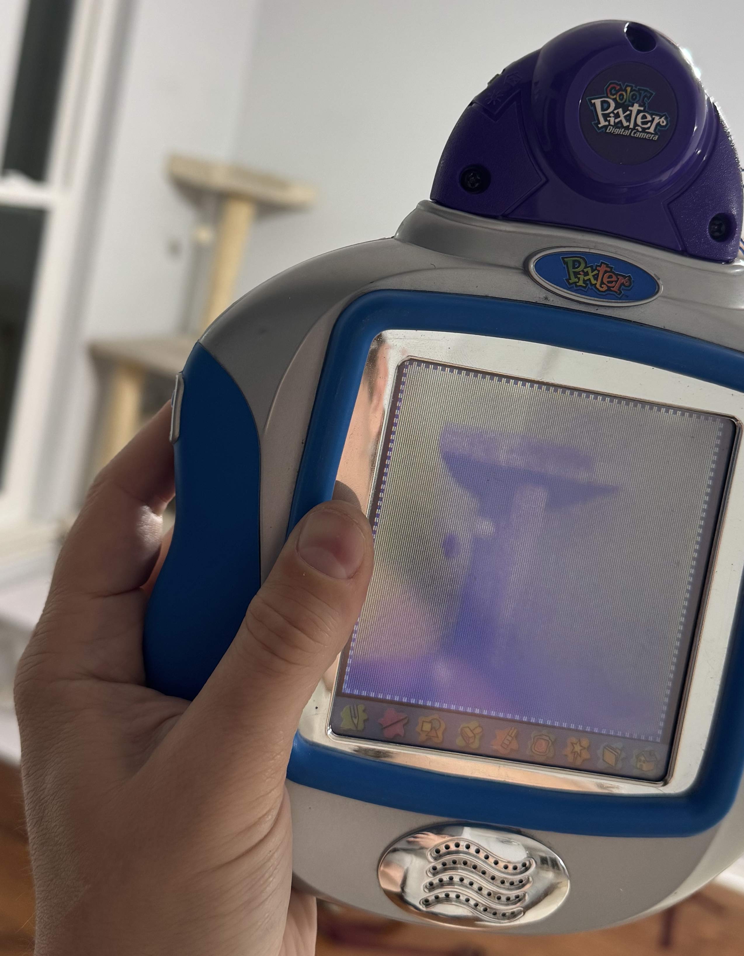
There was also this one cart that would be extra-hard to emulate, I knew -- the Pixter Camera. Officially billed as a "color" camera, I had no way to ascertain it since the Pixter Color's screen is barely able to display anything at all. I had hoped that I could try on the TFT Pixter Color. The camera cart did not work on it! I tried on the Pixter Multimedia! No joy either. It seems like the Pixter Camera only works on the original Pixter Color. This was a curious failure in the ecosystem which was clearly well designed for backwards compatibility. On one hand, it makes sense, Camera is a complicated hardware device which must be interacted with natively. On the other hand, i2c was like that too, and they found a way to make it work on Pixter Multimedia. What gives?
The Pixter Color Camera cart seems to have a lot of VM code and looks normal in all ways, except ... on boot it immediately jumps to native code and never again runs the ROM VM interpreter. What? Why? Then why have all that VM code in the cart? More research followed. So... the cart loads its own code to RAM and then runs it. Its own code is ... seemingly the very same VM interpreter, with a few opcodes added and slightly different setup. Why not just use NATIVE_CALLOUT_28 and NATIVE_CALLOUT_2C? Can you guess? The normal VM always runs in 8-bits-per-pixel paletted mode. But camera needs real colors. LH75411 can display 12 bits per pixel color. As the stock VM does not at all expose that capability, a new VM was needed. Also this is why it is incompatible with other hardware. Both the TFT Pixter Color and the Pixter Multimedia set up their display controllers entirely differently. The hardware is newer than the code in the cart and thus the code knows nothing about driving the new hardware. Again, a depressing failure.
Curiously, this cart COULD be updated. Unlike all others, the ROM in this one is actually a garden-variety NOR flash chip. I found no evidence that any such updates ever existed, but surely this was intended, since the NOR flash is more expensive than the blob-mask-ROM chip that all other carts have.
Well, we can at least discuss how the camera should and could work: There are two chip-select pins going into cart. One must necessarily go to the ROM, the other is for "other uses". Camera is such use. Logical so far... I did not reverse engineer more in this direction, since emulating the camera is somewhat meaningless. Emulating a readable memory at 0x4c000000 is enough for the ROM to run. Perhaps someone else will take it further? (wink wink)
Preserved and not-yet-preserved Games
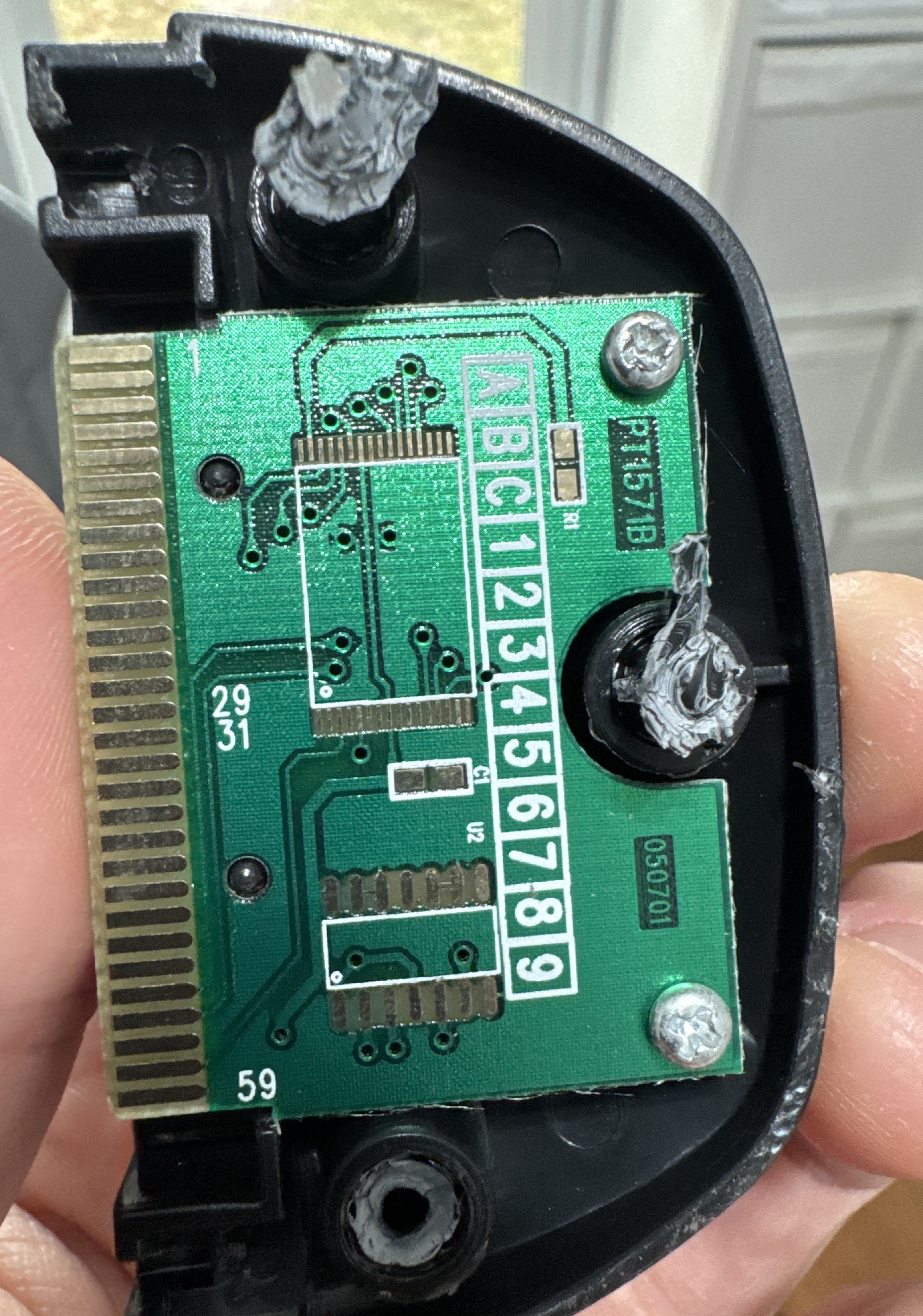
Which carts are Dumped? Thanks to Josh's efforts -- almost all of them. Along the way he even found what was (I think) was a marketing cart - complete outside, but entirey unpopulated untouched inside. Since the PCB is part of what holds a cart in the Pixter, a dummy cart still needed a PCB. What a rarity!
- Pixter Classic
- Action Art
- Arcade
- Art Safari
- Barbie Fashion Show
- Cool Wheels - Car Creations
- Crazy Word Factory
- Dinosaurs Dino Draw
- Discovery Kids Dinosaurs
- Disney Fun
- Enchanted Princess
- Learning Fun
- Learning Fun 2
- Maze Mania
- Monster Shop
- Music Studio (this one has a special Melody Chip)
- Music Video Creator
- On the Go Games
- Rescue Heroes Mission Masters
- Rocket Power
- SpongeBob SquarePants Aqua Adventure
- Sports Software
- Story Composer
- The Powerpuff Girls
- Toy Designer
- Pixter Color
- Mucha Lucha!
- Alphabet Forest (melody 6 never ends, even if not asked to loop)
- Color Arcade
- Arthur's Birthday
- Arthur
- Color Barbie Fashion Show
- Barbie 2 Writing
- Cars
- Clifford
- Digital Camera
- Creative Genius
- Cyberchase
- Color Dinosaurs DinoDraw
- Dora the Explorer
- Global Passport
- Hot Wheels
- Just Grandma and Me
- Math Mansion (melody 6 never ends, even if not asked to loop)
- Pet Shop
- Mazes, Puzzles & Games
- Color Rescue Heroes Mission Masters
- Scooby-Doo
- Spongebob Squarepants 2: Math Mania
- SpongeBob Squarepants Color Aqua Adventure
- Starter Learner Game
- Symphony Painter (this one has a very special Melody Chip)
- Teen Titans
- The Fairly OddParents
- Word Island (melody 17 never ends, even if not asked to loop)
- Pixter Multimedia
- The Best of Dora with Cartoon Creator Software
- The Best of Monster Jam World Finals 4 with Video Creator Software
- The Best of SpongeBob SquarePants with Cartoon Creator Software
- The Best of Winter X Games with Video Creator Software
- Walking with Dinosaurs with Scene Creator Software
- Winx Club with Scene Creator Software
- The Best of Yu-Gi-Oh!
Which games are not yet dumped? Only a few -- the ones that seem to never pop up on eBay, somehow. If you have one of these, or another game not listed in the list above please reach out.
- Pixter Classic
- Pirate's Treasure
- Pixter Color
- Atomic Betty
- The Angry Beavers
- Pixter Color
- The Best of Friday Night Nicktoons with Cartoon Creator Software
- The Best of LazyTown with Video Creator Software
Downloads
In addition to the various things linked to directly in the article, here is a code drop. Inside you'll find a few directories, each with its own license file.
ClassicDisasm
This is the disassembler for the classic games. It needs a raw binary flash dump. You can get that out of a PCI file. It produces output similar to the following. It is passable for game analysis and debugging.
0049e8: sub_0049e8: 0049e8: 47 MEMRD8 [0x07] ;CALL from loc_00506f ;CALL from loc_007aee ;CALL from loc_00691e ;CALL from loc_006917 ;CALL from loc_0061c9 ;CALL from loc_0061c2 ;CALL from loc_005a8d ;CALL from loc_005a86 0049e9: 00 PUSHIMM8 0x00 0049ea: c8 IS_EQ8 0049eb: f2 9f 4a BEQZ loc_004a9f 0049ee: 48 MEMRD8 [0x08] 0049ef: f3 01 02 4a SWITCHJMP 0x01, loc_004a02 0049f3: 03 PUSHIMM8 0x03 0049f4: ae PLAY_ADPCM 0049f5: 04 PUSHIMM8 0x04 0049f6: 9f SPECIAL_9F 0049f7: 00 PUSHIMM8 0x00 0049f8: 16 PUSHIMM8 0x16 0049f9: b0 MEMWR8 0049fa: ff DROP_TOP 0049fb: 04 PUSHIMM8 0x04 0049fc: 21 PUSHIMM8 0x21 0049fd: b0 MEMWR8 0049fe: ff DROP_TOP 0049ff: f0 9c 4a BRA loc_004a9c 004a02: loc_004a02: 004a02: f3 02 15 4a SWITCHJMP 0x02, loc_004a15 ;BRANCH from loc_0049ef 004a06: 03 PUSHIMM8 0x03 004a07: ae PLAY_ADPCM 004a08: 05 PUSHIMM8 0x05 004a09: 9f SPECIAL_9F 004a0a: 00 PUSHIMM8 0x00 004a0b: 16 PUSHIMM8 0x16 004a0c: b0 MEMWR8 004a0d: ff DROP_TOP 004a0e: 04 PUSHIMM8 0x04 004a0f: 21 PUSHIMM8 0x21 004a10: b0 MEMWR8 004a11: ff DROP_TOP
ColorDisasm
This is the disassembler for the color games. It needs a raw binary flash dump. You can get that out of a PCI file. It produces output similar to the following. It is passable for game analysis and debugging.
480052ba: sub_480052ba: ;CALL from loc_48007b92 480052ba: 0000 PUSHIMM #0x0000 480052bc: 297f 0087 NTV_CALL_2C #0x0087 ; push(i2_EEPROM_READ(pop())) 480052c0: 0aa6 IS_EQ push, pop, #0x00a6 480052c2: 00be PUSHIMM #0x00be 480052c4: 297f 0087 NTV_CALL_2C #0x0087 ; push(i2_EEPROM_READ(pop())) 480052c8: 0a6a IS_EQ push, pop, #0x006a 480052ca: 2960 AND 480052cc: f061 BEVEN loc_48005390 480052ce: 0001 PUSHIMM #0x0001 480052d0: 297f 0087 NTV_CALL_2C #0x0087 ; push(i2_EEPROM_READ(pop())) 480052d4: 24ff 0202 STH MEM16[#0x00404] 480052d8: a800 STRH #0x00, LOCAL_VARS16[#0x00] 480052da: loc_480052da: ;BRANCH from loc_480052e6 480052da: 2d00 RD_LOCAL LOCAL_VARS16[#0x00000] 480052dc: 0e20 IS_LT push, pop, #0x0020 480052de: f013 BEVEN loc_48005306 480052e0: e003 BRA loc_480052e8 480052e2: loc_480052e2: ;BRANCH from loc_48005304 480052e2: 2ec0 PUSH LOCAL_VARS16[#0x00000]++ 480052e4: 297e DROP_TOP 480052e6: e7fa BRA loc_480052da 480052e8: loc_480052e8: ;BRANCH from loc_480052e0 480052e8: 6502 MUL16 push, LOCAL_VARS16[#00], #0x02 480052ea: 0602 ADD push, pop, #0x0002 480052ec: 297f 0087 NTV_CALL_2C #0x0087 ; push(i2_EEPROM_READ(pop())) 480052f0: 0008 PUSHIMM #0x0008 480052f2: 296e LSL 480052f4: 6502 MUL16 push, LOCAL_VARS16[#00], #0x02 480052f6: 0603 ADD push, pop, #0x0003 480052f8: 297f 0087 NTV_CALL_2C #0x0087 ; push(i2_EEPROM_READ(pop())) 480052fc: 2964 ADD
PalmosLauncherMulti
This builds a cart image for a classic cart that demonstrates running different code on different hardware revisions. On Classic-like devices it shows an image and infinite loops. On Pixter Color it shows a high-res compressed image that is not pixel-doubled as a classic game would normally appear. On Pixter Multimedia it unpacks a huge package to RAM and jumps to it. This can be used as an inspiration for multi-system games that take advantage of all capabilities available in each system safely.
uM23
This builds a cart image for a classic cart that emulates Cortex-M23, and demonstrates a small ARM program that will then run in the emulator on the Pixter Classic/Plus/2.0. Since this is native 6502 code, it will, of course, not work on the Pixter Color/Multimedia. This is considered fine as (1) this is a proof of concept and (2) you do not need to emualte ARM on those - tey are alrady ARM devices.
uARMpixter
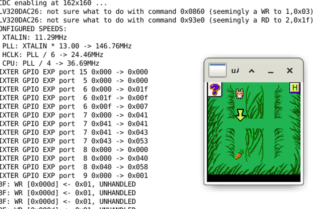
This is the ARM emulator for Pixter Color and Pixter Multimedia. You determine which one is emulated by uncommenting one of the lines in the Makefile
#pick a device DEVICE += $(PIXTER) $(LH754XX) devicePixterColor.o #DEVICE += $(PIXTER) $(LH795XX) devicePixterMultimedia.o mmiodev_PixterGpioExpander.o mmiodev_GPIONAND.o nand.o vBitbangedSPI.o i2s_spidev_TLV320DAC26.o
The usage is simple, the first param is the console ROM file (downloadable above in the article), then thefilename for the EEPROM that represents the in-Pixter memory. The file will be created if it does not exist. Then, optionally, a cart ROM to run that game, and then the eeprom name for cart save, if any. SDL2 is needed. Enjoy
The emulator does not draw the under-screen buttons, but they are there and clickable, you just have to imageine them
uPixter
This is the 6502 emulator for Pixter Classic/Plus/2.0. You determine which one is emulated by uncommenting one of th elines in the Makefile
#pick one!!!! CC_FLAGS += -DPIXTER_CLASSIC #CC_FLAGS += -DPIXTER_PLUS #CC_FLAGS += -DPIXTER_2_0
The usage is simple, the first param is the console ROM file (downloadable above in the article), then thefilename for the EEPROM that represents the in-Pixter memory. The file will be created if it does not exist. Then, optionally, a cart ROM to run that game, and then the eeprom name for cart save, if any. SDL2 is needed. Enjoy
The emulator does not draw the under-screen buttons, but they are there and clickable, you just have to imageine them
Appendix A - Pixter Color VM
What follows is my documentation on the VM. This is accurate enough to produce an HLE and to understand/interpret/modify games. Here are some important notes:
- immXe this means an X-bit immediate that is extendable. If the value represented by the bits is anything other than all ones, the value given is the value meant. If the value represented is all ones then the very next instruction stream halfword is the value. This makes the instruction longer and allows any 16-bit immediate to be represented by such fields. If an instruction is documented to be two halfwords long already, this extension halfword comes BEFORE the second halfword of the instruction. This is important!
- All stack locations are internally stored as 32-bit words and work that way except where specified otherwise. This means that pushing a 32-bit value is possible, but many operations only operate on 16 bits anyways
- When used in pseudocode here, push() and pop() are direct stack ops, 32 bits in size. peek() looks at the top 32-bit stack value but does not pop it
- popFirst(), popSecond(), popThird(), and so on are pop() operations, named such to make it clear the order of operations. The same applies to push ops with similar names
- When used in pseudocode here, MUL16() explicitly and on purpose truncates its results so that only the lower 16 bits are produced..., MUL() does not do that. Other ops not explicitly stated to truncate, do not...
- All comparisons are done as unsigned numbers
- Memory:
- Data memory layout is: [global memory] [local mem of top level func] [local mem of next level func] [local mem of leaf func]
- Notation such as MEM16[x] literally means *(uint16_t*)(((char*)MEM) + x), as in a 16 bit vaue as BYTE offset x. this is simpler than multiplying/dividing by 2 everywhere
- MEM[] ops addresses global memory
- LOCAL_VARS16[] ops address local memory
- Function call hides local mem from called func, giving it a new clean sheet starting at zero
- Function return unwinds the above
- The start of global memory is MEM_START, and is equal to &MEM[0]
- The size of global memory, in bytes, is 2 * the value in word pointed to by the word at offset 0x14 from cart start. More on cart headers later
- All pointer math depicted in this document is done as if memory was "char-addressed", so &arry_of_u16s[1] - &arry_of_u16s[0] will be 2, not 1 as it would be in normal C. This simplifies explanations.
Pixter Color VM instructions
How to use the opcode table: match an instruction halfword with this table top to bottom till you find a match among the listed bit values. More specific decode options are higher up. This gives you instruction format. The scroll down to the docs for that instruction format to see what the instr is.
TYPE A instrs
There is only one TYPE A instruction - PUSHIMM. It pushes a given immediate unto the stack.
TYPE B instrs
Type B instructions are mostly ALU ops with immediate or memory right-hand-side operands.
TYPE C instrs
Type C instructions do memory loads or stores, loads load from memory and push to stack, stores pop from stack and store to memory. You'll note that address generatation for these is the same for both laods and stores and the "is store" bit is the top of "op"
TYPE D instrs
There is only one TYPE D instruction - PUSHLONG. This is a two-word instruction, it pushes the value equal to the immediate encoded in the instruction (extended as needed), shifted left 16, plus the value of the very next inbstruction stream halfword. This means that many 24-bit constants can be pushed using 4 bytes of instruction, and any 32-bit value can be pushed using 6 bytes of instruction. Recall the ordering of the extended first instruction halfword vs the second halfword.
TYPE F instrs
This format encompases more ALU ops, mostly targeting global memory and locals. It also includes some indexing helpers
TYPE G instrs
| op | operation |
|---|---|
| 00110 | AND |
| 00111 | ORR |
| 01000 | EOR |
| 01001 | UMOD |
| 01010 | ADD |
| 01011 | SUB |
| 01100 | MUL16 |
| 01101 | UDIV |
| 01110 | IS_EQ |
| 01111 | IS_NE |
| 10000 | IS_GT |
| 10001 | IS_GE |
| 10010 | IS_LT |
| 10011 | IS_LE |
This format encompases more ALU ops, they do not touch the stack. They are a fast way to operate on low-numbered locals and globals, those thus being "faster". These also can encode small immediates in the instr. Each instr has an "A" field and a "B" field. Those are used differently based on the "mode" field. Actual ALU op is chosen by the "op" field.
TYPE H instrs
This format allows easily loading a small immediate into a global or a local variable.
TYPE J instrs
There is only one instruction of this format. It loads a constant with a given index from the constant table and piushes it onto the stack. The actual operation is push(CONSTANTS16[2 * imm12e + 2 * pop()])
TYPE K instrs
There is only one instruction of this format -- it is the subroutine call. This is a two-halfword-long instruction. The second halfword is composed of two 8-bit fields. The high byte is "A" and the low byte is "B". Note that the first halfword has an extendable immediate, so the second halfword of the instruction might in fact be third. The VM supports function calls with quite a lot of handholding, so the full operation of this opcode is shown here. The field I call "A" determined how many of the values currently on stack are parameters to the called funcrtion. The field "B" is how many locals the calling function has. That the pushed return address is the address of the last instruction halfword is interesting, but actually it makes sense - the return code needs these two values again, so storing the pointer to them is logical. so, what does CALL do?
- push(full 32-bit address of last instr halfword)
- vPC = CONSTANTS + imm13e * 2 //yes this is correct, constants table will have a jump instr in it
- increment LOCAL_VARS pointer by B * 2 (this should hide all local vars of this func from the callee)
- move top value on the stack (our return address) BELOW "A" stack slots (those are params)
TYPE L instrs
These three instructions are relative branches. Two are conditional and one is not. A curious fact is that unlike what many CPUs do: "branch on zero" and "branch on non-zero", these are instead "branch on odd" and "branch on even". That is to say that they are "branch on zero" and "branch on non-zero", but they only consider the lowest bit of the stack value. Some interesting uses of this are possible. The encoding of the branch offsets is also interesting. There is no way to encode an offset of zero, and thus no way to encode a one-instruction-long infinite loop. The offset calcultion is as follows: first, sign-extend the 11-bit immediate, then, if it is not negative, add one, this makes the range backwards and forwards symmetrical. Then add twice the resulting value to the address of the current instruction to calculate the destination address.
TYPE M instrs
This instr format is used to implement CASE - a switch()-like construct. This instruction format also uses two halfwords, with the entire second one storing the compare-to-value. The actual logic that this instruction executes is as follows. Clearly, the idea is to build a sequence of these to jump over every possible case until the correct one is found, with the switched-on value being on the stack. The jumps can only be forward, further making this the likely intended use-case.
if (peek() != compare-to-value) { vPC = adr_of_this_instr + 2 + 2 * imm11; } else { pop() }
TYPE E instrs
This instr format is used to implement variosu Pixter-specific things, since you noticed that all other instructions are completely generic and have nothing to do with Pixter. Also in here are no-operand opcodes, like RET. Many lines of pseudocode here will references other pseudocode lower down. As 127 possible instrucions are encodeable in thius format, I give their "op" values in hex instead of binary. some instrs are clearly doing nothing useful, and most of those are never called by any game. "USED" columsn lists if an instr is known to be used by any known game.
Pixter Color Cart Header
Cart is seen in the address pace at 0x48000000. this is hardwired on Pixter Color, and while Pixter Multimedia has an MMU, for obvious reasons of backwards compatibility, the cart is also mapped there at the same address. What reasons? Many of the header fields are not offsets burt actual addresses, basd at ... 0x48000000. Only the values that are ever read at all are listed here.
Pixter Multimedia Cart Header
Pixter Multimedia Cart header is seen in the 0th page of the 0th NAND block and is muhc simpler. The specified byte amount will be copied from cart start (incl this header) to the given RAM address. Then, with cp15, c1 set to 0x70, an ARM-mode jump will be made to 0x200 + copy destination. This header format is allowed not only on NAND carts but also on normal parallel flash carts.
Pixter Color VM structures
Object Table
The object tabel lists all objects in the game. It is used as an index to find them. What are objects? Anything that is not code is an object, mostly. Examples are: images, color tables, sounds, etc. Objects themselves do not have a "type", they are each simply a bag of bytes with a start address. Nothing stops the same object from being a sound effect and a color table, if you are clever enough. They do not have a stored size either, like I said - only a start address. The start of the Object Table itself is stores in the cart header at offset 0x18. What is the format of the object table? First there is a word that has the absolute address of the second word. Yes, semi-self-referential. The second word is the number of objects in the table. Then come the pointers to objects. Object indices are one-based so the first pointer is for object number 1, not 0.
Color Tables
A color table is an object of size 514. The first two bytes are unused, after that, come precisely 256 16-bit color entries in XRGB444 format. That is all.
4-to-16 maps
For better storage efficiency, some bitmaps are stored in a 4-bits-per-pixel format, which limits them to 16 colors. But as the console always runs in 8 bits per pixel mode, how does one pick which 16 of those 256 colors to use? One solution might be to say that the first 16 are used, but this woufl be limiting, so instead there is a table tah maps each 4 bpp color to an 8-bit index into the proper full color table. The SET_GLOBAL_4_to_8_CLUT opcode can set which map top use by provinging the object index to the map. Object index 1 in every cart is NECESSARILY a 4-to-16 map, and it will be loaded at game start.
Audio Objects
Audio efects are stores in an ADPCM format, with a 48-byte header that is always entirely ignored. Pixter's ADPCM streams include inline signaling to signify stream end, and thus no length tracking is needed or provided
Font Objects
struct FontObj { u16 offsets[] //in halfwords, each //points to a CharImage struct CharImage { u8 width; u8 height; u8 data[]; } }
Font objects describe fonts that can be used to draw text. Each font is a collection of character images, each of which has a unique height and width. Pixels are stored at one byte per pixel, which might lead you to think that fonts can be color. This is false. The value of 0xFF means transparent and any other value means opaque, filled with the "text foreground color" (UI setting 3). Each font can draw up to 224 unique characters, the lowest supported code is 0x20. That is to say that if you attempt to draw a character with a lower code, it will be ignored. Else, 0x20 is subtracted and that resulting value is used as an index into the offsets table. The value there multiplied by two is added to the start of the font object to find a CharImage object which describes a character image. If a character width is odd, it is stored as if it was one pixel wider. That last column will not be drawn.
Larger Image
struct LargerImage { u16 w; u16 h; u8 flags; u8 objIdx4to8bppMap; u8 data[]; }
Why larger? Because there are smaller image formats in Pixter Classic, and this is what I named this while reverse engineering it and I decided to keep it. Deal with it! These images can be compressed, and they can have a transparent color. Curiously, uncompressed images cannot have transparency. The compression is RLE, with a few differences based on whether the image is stored with 4 or 8 bits per pixel. As previously mentioned, 4-bits-per-pixel images are expanded to the 8-bits-per-pixel palette using a 4-to-16 map object. There is a global setting for the default one, but each image can also specify its own. The flags field is split into some sub-fields. The bottom four bits describe the compression used. The top bit is the "isCompressed" flag. There are two compression types: one is represented by the type field value of 8, and the other is used in all other cases. Decompression algorithms for both are given below. As you can see, there is a field to set the 4-to-16 map object index, but you'll also note that it is only 8 bits in size, thus limiting the object index that can be represented. This leads most games to cluster their 4-to-16 map objects at the start of the object table since no other part of the VM limits object indices to 8 bits.
The drawing itself is affected by the "flags" setting passed to the DRAW_OBJ_IMAGE or the DRAW_RAM_IMAGE opcode. As they share the drawing core, those flags are explained here. the parsing of the flags field is ... curious and explained below. Whenever an image is drawn, a "dirty buffer" is also affected. This is another memory buffer where a bit is allocated per pixel. If a given image pixel is drawn, the dirty buffer's bit is also changed. Depending on the image mode it may be set or cleared. This later allows using the dirty buffer as a mask for other ops.
The image decompression code is also given below
- 0x00 - no transparency, use last-used 4-to-8-CLUT if needed, dirty buffer in CLEAR mode
- 0x01..0x7F - transparent color given by UI setting 2, use last-used 4-to-8-CLUT if needed, dirty buffer in CLEAR mode
- 0x80 - no transparency, use per-image 4-to-8 CLUT given in image header, dirty buffer in CLEAR mode
- 0x81, 0x83..0xFF - transparent color given by UI setting 2, use per-image 4-to-8 CLUT given in image header, dirty buffer in CLEAR mode
- 0x82 - transparent color given by ui_setting_2, use per-image 4-to-8 CLUT given in image header, dirty buffer in SET mode
Decompress8bpp: while (rleRepeatedValue = *src++, rleRepeatsLeft = *src++) { while (rleRepeatsLeft--) *dst++ = rleRepeatedValue; } Decompress4bpp: while (1) { rleRepeatedValue = *src / 16; rleRepeatsLeft = *src++ % 16; if (!rleRepeatsLeft) rleRepeatsLeft = *src++; if (!rleRepeatsLeft) break; while (rleRepeatsLeft--) *dst++ = 4BPP_to_8BPP_MAP[rleRepeatedValue]; }
Audio effects
Pixter color is capable of playing ADPCM sound effects in the background of the game at an 8KHz sampling rate using interrupts and a PWM unit for analog output. Quality is ... not great. sicne "ADPCM" means many things ot many people, the precise decoder used is presented here. One cool feature of the bitstream format used in Pixter is that "end of sound" marker is embedded in the data itself, thus requiring no tracking of data length by the playback code. The output of the ADPCM decoder is an unsigned 8-bit sample value. The input is a nibble from the input data stream. Since the incoming data is a stream of bytes, the nibble order is important. Pixter considers the higher nibble to be the earlier sample. The decoder has two bytes of state: predictor which is inited to 0x80 and stepSize which is inited to 0x00
const u8 adpcmTab1[] = { 0, 1, 2, 3, 4, 5, 7, 9, 1, 2, 3, 4, 5, 7, 9, 13, 2, 3, 5, 8, 12, 17, 23, 30, 3, 6, 11, 18, 27, 38, 51, 66, 4, 9, 14, 24, 34, 44, 64, 84, 5, 11, 17, 29, 41, 53, 77, 101, 6, 13, 20, 34, 48, 62, 90, 118, 7, 15, 23, 39, 55, 71, 103, 125, }; const u8 adpcmTab2[] = { 0x00, 0x00, 0x00, 0x00, 0x00, 0x00, 0x08, 0x08, 0x00, 0x00, 0x08, 0x08, 0x08, 0x08, 0x10, 0x10, 0x08, 0x08, 0x10, 0x10, 0x10, 0x10, 0x18, 0x18, 0x10, 0x10, 0x10, 0x18, 0x18, 0x20, 0x20, 0x28, 0x18, 0x18, 0x18, 0x20, 0x20, 0x28, 0x28, 0x30, 0x20, 0x20, 0x28, 0x28, 0x28, 0x28, 0x30, 0x38, 0x28, 0x28, 0x30, 0x30, 0x30, 0x30, 0x38, 0x38, 0x30, 0x30, 0x38, 0x38, 0x38, 0x38, 0x38, 0x38 }; AdpcmGetNextSample(inNibbble): tmp0 = ((inNibbble >> 1) & 7) | stepSize; if (!tmp0 && (inNibbble & 1)) AUDIO IS OVER. STOP PLAYBACK stepSize = adpcmTab2[tmp0]; if (inNibbble & 1) predictor -= adpcmTab1[tmp0]; else predictor += adpcmTab1[tmp0]; return predictor ^ 0x7F;
Color UI Layout
This is the structure that is used by UI_PROCESS_TAP opcode. None of this is so specialized that is cannot be done by normal VM code, but the ROM provides this to simplify. You describe your UI shape, and it can tell you which button a given tap pressed. The description format is as follows: First a button is described using 4 8-bit values: width, height, x, y. This is button #1 (they are 1-indexed). If more buttons of the same size exist, for each next button, only x and y coordinates are listed. If more buttons exist, but they are of different size, the byte 0xFE is inserted, and then we begin again by describing button width and height, x and y. At the end of the list of all buttons, the byte 0xFF is inserted.
As the game may have multiple layouts, they are all stored in a table. I suspect this was a late addition to the VM design, since there is no reason at all why UI Layouts would not be in the object table, except they are not. They get their own table, which is referenced from the cart header at offset 0x08
UI Settings
In a number of places you'll have seen references to "UI Settings". This is basically just a set of 16-bit values that can be set via the SET_UI_SETTING opcode. Not all settings are fully decoded yet, but the ones I see used are.
- 0x00 - brush color for drawing
- 0x01 - ObjectID of a bitmap representing the brush shape
- 0x02 - 8-bit color index to treat as transparent when drawing 8bpp images
- 0x03 - 8-bit color index for the fore color of text drawn using PUTCHAR
- 0x07 - current audio volume, 0 = max, 4 = mute
- 0x08 - number of bits needed to represent MelodyID to the current Melody Chip
Appendix B - Pixter Classic VM
What follows is my documentation on the VM. This is accurate enough to produce an HLE and to understand/interpret/modify games. Here are some important notes. The VM in the 6502-based Pixter devices uses the host stack as the VM stack, so overflowing the host stack is doable. Be careful. When pushing multi-byte values onto the stack, here are the pseudo-ops I use:
- pop2() = popFirst() * 256 + popSecond()
- pop3() = popFirst() * 65536 + popSecond() * 256 + popThird();
- push2(val) = push(val & 0xff); push(val >> 8);
- push3(val) = push(val); push(val >> 8); push(val >> 16);
Some classic VM opcodes' behaviour differs between classic, plus, 2.0, and color/multi and that is OK as long as no games use it -- the ROM game can since the ROM game is developed together with that specific VM. Differences are noted in the table as best as I was able to ascertain them
Pixter Classic VM instructions
How to use the opcode table: match an instruction halfword with this table top to bottom till you find a match among the listed bit values. More specific decode options are higher up. This gives you instruction format. The scroll down to the docs for that instruction format to see what the instr is.
| 7 | 6 | 5 | 4 | 3 | 2 | 1 | 0 | BITS/use |
|---|---|---|---|---|---|---|---|---|
| 00 | imm6 | push(imm6) | ||||||
| 0100 | imm4 | push(MEM8[imm4]) | ||||||
| 0101 | imm4 | MEM8[imm4] = pop() | ||||||
| 1011 | op | ALU | ||||||
| 11 | op | |||||||
| op | SPECIAL | |||||||
ALU ops
Some instructions are more than one byte long. That will be explained in the description if so
SPECIAL ops
The remainder of the decode space is made up of special operations, each with its own purpose and meaning. They are detailed here, with notes about differences in behaviour on different platforms. You'll note that sometimes Pixter Color/Pixter Multimedia are mentioned. As they have a VM for compatibility with classic carts via the adapter, their implementations are also instructive. The "op" listed is literally the byte value of the instruction. When a description says "same as 0x.." that does not simply mean that the operation is the same, that means that the same exact code runs (same jump targets), this means that this is not accidentally similar code but purposefully same handler implying same purpose. You'll also note that some opcodes have different stack effects between different Pixter variants. These opcodes thus by definition cannot be used in any published games. They can be used in the ROM game itself though. Sometimes multiple opcodes map to the same code. This is reflected in the table by merging rows.
Pixter Classic Structures
Pixter Classic Cart Header
The cart header for pixter classic is seen at the given addresses when cart page 0 is selected
Classic UI Layout
u8 numChunks; Chunk { u8 numCols; u8 numRows; Column { u8 left, right } [numCols]; Row { u8 top, bottom; } [numRows] } [numChunks];
This is the structure that is used by GET_PEN opcode. None of this is so specialized that is cannot be done by normal VM code, but the ROM provides this to simplify. You describe your UI shape, and anytime you get pen status, the info of whether a button was tapped is also provided. Also provided is the info on whether any of the soft buttons under-screen were tapped. The layout is described by a structure shown here. This layout is optimized for grids of buttons and indeed all UIs are built around this primitive.
Classic Image and Sound lookup
This is how you find an image or a sound given its index and the current scene. An address is composed of a ROM page (0..31) and an address therein (0x4000..0xbfff).
//looks up an image by scene index and image index. SCENE_INDEX is set by opcode 0xA6. //If it is zero, built-into-ROM images are used //image indices are also not allowed to be 0. it DOES work but no game does it, instead at index [0] in each //sceneImgListPtr, the number of images contained in the scene is stored FindImage(imgIdx) { u16 sceneImgListPtr = ROM16[0xbf04] + SCENE_INDEX; u16 imgPtrPtrPtr = ROM16[sceneImgListPtr] + 2 * imgIdx; u16 imgPtrPtr = ROM16[imgPtrPtrPtr]; u16 imagePtr = ROM16[0xbf0a] + imgPtrPtr; u16 imageData = ROM16[imagePtr]; u8 imagePage = ROM8[imagePtr + 2]; if (imageData >= 0xc000) imageData -= 0x8000; imagePage--; } //looks up an ADPCM object by index FindADPCM(soundIdx) { u16 audioPtrPtr = ROM16[0xbf08] + 3 * (soundIdx - 1) u16 audioPtr = ROM16[0xbf0a] + audioPtrPtr; u16 audioData = ROM16[audioPtr]; u8 audioPage = ROM8[audioPtr + 2]; if (audioData >= 0xc000) audioData -= 0x8000; audioPage--; }
Classic Image Format and compression
This is the format of a Classic image and how to decompress it. Indeed it is unnecessarily complex. I do not know why.
CLASSIC_IMAGE { u8 widthAndCompressedFlag; u8 height; u8 data[stride * height]; //stride = (actualWidthidth + 7) &~ 7; } //actualWidthidth is (widthAndCompressedFlag & 0x7F) //isCompressed is (widthAndCompressedFlag & 0x80) //cart images can be compressed. images in pixter ROM itself seem to //never be (Decompression never considered for them) DRAW_MODE is: 0 = draw only 00-valued pixels 1 = draw only FF-valued pixels 4 = draw all pixels else = invert 00 valued pixels only DECOMRESSION: struct DecompressState { u8 decompressed[30]; u8 flags; //@0x1e u8 idx; //@0x1f //32 bytes in size to here const u8* src; u8 bitBuffer, bitMask; }; static u8 getBit(struct DecompressState *state) { if (!(state->bitMask >>= 1)) { state->bitBuffer = *state->src++; state->bitMask = 0x80; } return (state->bitBuffer & state->bitMask) ? 0x00 : 0xff; } //to be called once at image start void decompressInit(struct DecompressState *state, const u8* img) { state->src = img; state->bitMask = 1; state->flags = getBit(state) == 0xff ? 0 : 2; state->flags += getBit(state) == 0xff ? 0 : 1; } //to be called to decode the run length u8 classicImgCompressionGetRunLength(struct DecompressState *state, u8 curPolarity) { static const uint8_t decompressTab0[] = { 2, 3, 3, 3, 4, 4, 5, 5, 6, 6, 6, 7, 7, 7, 7, 7, 7, 8, 8, 8, 8, 8, 8, 8, 8, 8, 8, 8, 9, 9, 9, 9, 9, 9, 9, 9, 9, 9, 9, 9, 9, 9, 0xA, 0xA, 0xA, 0xA, 0xA, 0xA, 0xA, 0xA, 0xA, 0xA, 0xB, 0xB, 0xB, 0xB, 0xB, 0xB, 0xB, 0xB, 0xB, 0xB, 0xB, 0xB, 0xB, 0xB, 0xB, 0xB, 0xB, 0xB, 0xB, 0xB, 0xB, 0xB, 0xB, 0xB, 0xB, 0xB, 0xB, 0xB, 1, 0, 2, 3, 4, 5, 6, 7, 8, 9, 0xA, 0xB, 0xC, 0xD, 0xF, 0x36, 0x3E, 0xE, 0x10, 0x11, 0x12, 0x15, 0x16, 0x17, 0x1E, 0x22, 0x40, 0x4C, 0x13, 0x14, 0x18, 0x19, 0x1A, 0x1C, 0x1D, 0x20, 0x39, 0x3C, 0x3F, 0x44, 0x48, 0x4E, 0x1B, 0x1F, 0x21, 0x23, 0x2D, 0x2E, 0x30, 0x33, 0x34, 0x4B, 0x24, 0x25, 0x26, 0x27, 0x28, 0x29, 0x2A, 0x2B, 0x2C, 0x2F, 0x31, 0x32, 0x35, 0x37, 0x38, 0x3A, 0x3B, 0x3D, 0x41, 0x42, 0x43, 0x45, 0x46, 0x47, 0x49, 0x4A, 0x4D, 0x4F}; static const uint8_t decompressTab1[] = { 2, 2, 3, 4, 4, 5, 5, 6, 6, 6, 7, 7, 7, 7, 7, 8, 8, 8, 8, 8, 8, 9, 9, 9, 9, 9, 9, 9, 9, 9, 9, 9, 9, 9, 9, 9, 9, 9, 9, 9, 9, 9, 0xA, 0xA, 0xA, 0xA, 0xA, 0xA, 0xA, 0xA, 0xA, 0xA, 0xA, 0xA, 0xA, 0xA, 0xA, 0xA, 0xA, 0xA, 0xA, 0xA, 0xA, 0xA, 0xA, 0xA, 0xA, 0xA, 0xA, 0xA, 0xA, 0xA, 0xA, 0xA, 0xA, 0xA, 0xA, 0xA, 0xA, 0xA, 1, 2, 5, 0, 4, 3, 6, 7, 8, 9, 0xA, 0xB, 0xC, 0xD, 0xE, 0xF, 0x10, 0x11, 0x12, 0x14, 0x17, 0x13, 0x15, 0x16, 0x18, 0x19, 0x1A, 0x1B, 0x1C, 0x1D, 0x1E, 0x1F, 0x20, 0x21, 0x22, 0x23, 0x24, 0x25, 0x26, 0x40, 0x4C, 0x4E, 0x27, 0x28, 0x29, 0x2A, 0x2B, 0x2C, 0x2D, 0x2E, 0x2F, 0x30, 0x31, 0x32, 0x33, 0x34, 0x35, 0x36, 0x37, 0x38, 0x39, 0x3A, 0x3B, 0x3C, 0x3D, 0x3E, 0x3F, 0x41, 0x42, 0x43, 0x44, 0x45, 0x46, 0x47, 0x48, 0x49, 0x4A, 0x4B, 0x4D, 0x4F}; static const uint8_t decompressTab2[] = { 2, 4, 4, 4, 5, 5, 5, 5, 5, 5, 5, 5, 6, 6, 6, 6, 6, 6, 6, 6, 6, 7, 7, 7, 7, 7, 7, 7, 7, 8, 8, 8, 8, 8, 8, 8, 8, 8, 8, 8, 8, 8, 8, 8, 8, 9, 9, 9, 9, 9, 9, 9, 9, 9, 9, 9, 9, 9, 0xA, 0xA, 0xA, 0xA, 0xA, 0xA, 0xA, 0xA, 0xA, 0xA, 0xA, 0xA, 0xA, 0xA, 0xA, 0xA, 0xA, 0xA, 0xA, 0xA, 0xA, 0xA, 0, 1, 2, 3, 4, 5, 6, 7, 8, 9, 0xA, 0xC, 0xB, 0xD, 0xE, 0xF, 0x10, 0x11, 0x12, 0x13, 0x16, 0x14, 0x15, 0x17, 0x18, 0x19, 0x1A, 0x1D, 0x2A, 0x1B, 0x1C, 0x1E, 0x1F, 0x20, 0x21, 0x22, 0x23, 0x24, 0x25, 0x26, 0x27, 0x29, 0x2D, 0x30, 0x36, 0x28, 0x2B, 0x2C, 0x2E, 0x2F, 0x31, 0x32, 0x33, 0x34, 0x35, 0x37, 0x39, 0x3E, 0x38, 0x3A, 0x3B, 0x3C, 0x3D, 0x3F, 0x40, 0x41, 0x42, 0x43, 0x44, 0x45, 0x46, 0x47, 0x48, 0x49, 0x4A, 0x4B, 0x4C, 0x4D, 0x4E, 0x4F}; static const uint8_t decompressTab3[] = { 1, 3, 3, 4, 5, 5, 6, 6, 7, 7, 8, 8, 8, 9, 9, 9, 9, 9, 9, 9, 9, 9, 9, 9, 9, 9, 0xA, 0xA, 0xA, 0xA, 0xA, 0xA, 0xA, 0xA, 0xA, 0xA, 0xA, 0xA, 0xA, 0xA, 0xA, 0xA, 0xA, 0xA, 0xA, 0xA, 0xA, 0xA, 0xA, 0xA, 0xA, 0xA, 0xA, 0xA, 0xA, 0xA, 0xB, 0xB, 0xB, 0xB, 0xB, 0xB, 0xB, 0xB, 0xB, 0xB, 0xB, 0xB, 0xB, 0xB, 0xB, 0xB, 0xB, 0xB, 0xB, 0xB, 0xB, 0xB, 0xB, 0xB, 1, 2, 3, 0, 4, 5, 6, 7, 8, 9, 0xA, 0xB, 0xC, 0xD, 0xE, 0xF, 0x10, 0x11, 0x12, 0x13, 0x14, 0x15, 0x17, 0x19, 0x20, 0x22, 0x16, 0x18, 0x1A, 0x1B, 0x1C, 0x1D, 0x1E, 0x1F, 0x21, 0x23, 0x24, 0x25, 0x26, 0x27, 0x28, 0x29, 0x2A, 0x2B, 0x2C, 0x2E, 0x2F, 0x30, 0x33, 0x34, 0x36, 0x37, 0x43, 0x46, 0x4C, 0x4E, 0x2D, 0x31, 0x32, 0x35, 0x38, 0x39, 0x3A, 0x3B, 0x3C, 0x3D, 0x3E, 0x3F, 0x40, 0x41, 0x42, 0x44, 0x45, 0x47, 0x48, 0x49, 0x4A, 0x4B, 0x4D, 0x4F}; static const uint8_t decompressTab4[] = { 3, 3, 3, 4, 4, 5, 5, 5, 5, 5, 5, 5, 5, 6, 6, 6, 6, 6, 6, 6, 7, 7, 7, 7, 7, 7, 7, 8, 8, 8, 8, 8, 8, 8, 8, 8, 9, 9, 9, 9, 9, 9, 9, 9, 0xA, 0xA, 0xA, 0xA, 0xA, 0xA, 0xA, 0xA, 0xA, 0xA, 0xA, 0xA, 0xA, 0xA, 0xA, 0xA, 0xA, 0xA, 0xA, 0xA, 0xA, 0xA, 0xA, 0xA, 0xA, 0xA, 0xA, 0xA, 0xA, 0xA, 0xA, 0xA, 0xA, 0xA, 0xA, 0xA, 0, 1, 4, 2, 3, 5, 6, 7, 8, 9, 0xB, 0xC, 0xD, 0xA, 0xE, 0xF, 0x10, 0x11, 0x12, 0x13, 0x14, 0x15, 0x16, 0x17, 0x18, 0x19, 0x1E, 0x1A, 0x1B, 0x1C, 0x1D, 0x1F, 0x20, 0x21, 0x22, 0x4E, 0x23, 0x24, 0x25, 0x29, 0x2A, 0x2B, 0x2C, 0x2D, 0x26, 0x27, 0x28, 0x2E, 0x2F, 0x30, 0x31, 0x32, 0x33, 0x34, 0x35, 0x36, 0x37, 0x38, 0x39, 0x3A, 0x3B, 0x3C, 0x3D, 0x3E, 0x3F, 0x40, 0x41, 0x42, 0x43, 0x44, 0x45, 0x46, 0x47, 0x48, 0x49, 0x4A, 0x4B, 0x4C, 0x4D, 0x4F}; static const uint8_t decompressTab5[] = { 1, 3, 4, 4, 5, 5, 6, 6, 7, 7, 8, 8, 9, 9, 9, 9, 9, 9, 9, 9, 9, 9, 9, 9, 9, 9, 9, 9, 9, 9, 9, 9, 9, 9, 9, 9, 9, 9, 9, 9, 9, 9, 9, 9, 9, 9, 9, 9, 9, 9, 9, 9, 9, 9, 9, 9, 9, 9, 9, 9, 9, 9, 9, 9, 9, 9, 9, 9, 9, 9, 9, 9, 9, 9, 9, 9, 9, 9, 9, 9, 1, 2, 3, 4, 5, 7, 0, 6, 8, 9, 0xA, 0xB, 0xC, 0xD, 0xE, 0xF, 0x10, 0x11, 0x12, 0x13, 0x14, 0x15, 0x16, 0x17, 0x18, 0x19, 0x1A, 0x1B, 0x1C, 0x1D, 0x1E, 0x1F, 0x20, 0x21, 0x22, 0x23, 0x24, 0x25, 0x26, 0x27, 0x28, 0x29, 0x2A, 0x2B, 0x2C, 0x2D, 0x2E, 0x2F, 0x30, 0x31, 0x32, 0x33, 0x34, 0x35, 0x36, 0x37, 0x38, 0x39, 0x3A, 0x3B, 0x3C, 0x3D, 0x3E, 0x3F, 0x40, 0x41, 0x42, 0x43, 0x44, 0x45, 0x46, 0x47, 0x48, 0x49, 0x4A, 0x4B, 0x4C, 0x4D, 0x4E, 0x4F}; static const uint8_t *decompressTabsA[4] = {decompressTab0, decompressTab1, decompressTab2, NULL}; static const uint8_t *decompressTabsB[4] = {decompressTab3, decompressTab4, decompressTab5, NULL}; u8 cmpVal = 0, tabPos = 0, readVal = 0, matchVal = 0; const u8 **tabs = curPolarity ? decompressTabsA : decompressTabsB while(1) { while (tabs[state->flags][tabPos] != cmpVal) { cmpVal++; matchVal *= 2; readVal = readVal * 2 + (getBit(state) != 0xff ? 1 : 0); } if (readVal == matchVal) return tabs[state->flags][tabPos + 80]; matchVal++; tabPos++; } } //to be called to decompress each next row produces the ROW in state->decompressed void decompressNextRow(struct DecompressState *state) u8 curPolarity; state->idx = 0; memset(state->decompressed, 0, sizeof(state->decompressed)); curPolarity = getBit(state); do { u8 runLength = classicImgCompressionGetRunLength(state, curPolarity); if (!runLength) //0 means till end of line runLength = state->idx - CUR_IMAGE_WIDTH; if (curPolarity) { //set bits do { state->decompressed[state->idx / 8] |= 0x80 >> (state->idx % 8); state->idx++; } while (--runLength); } else { //clear bits (no work needed since we pre-zeroed the buffer) state->idx += runLength; } curPolarity ^= 0xff; //polarity changes } while (state->idx < CUR_IMAGE_WIDTH); }
EEPROM use in Pixter Classic/2.0
Appendix C - connections and pinouts
For all cart pinouts, the pin numbering works as follows. Imagine the cart lying on the table, front (colorful label) on top, connector facing you as you look into the connector. The top side of the connector is numbered from your left to your right in odd numbers: 1, 3, 5, and so on till 59. The bottom side is numbered also from your left to right, in evens: 2, 4, 6, and so on till 60. For Pixter Classic connector, the rules are the same, except that the numbering only goes to 20. Why this order? Some carts are actually labeled and this is the numbering they all use. To avoid confusion, we adopt it too.
Pixter Classic cart
Most carts have the pins listed here together shorted in the cart. Inside Pixter, they are not shorted, but one is n/c.
Pixter Classic to Color adapter
Refer to the above section for signal names. Here they are mapped to the Color Cart slot.