Today I chose, unwisely to try and get Rust compiled and flashed onto the Arduino Uno R4, which has a Renesas RA4M1 (Arm Cortex-M4) chip. There is a rust hardware abstraction layer crate for this chip, as well as a compile target.
I failed spectacularly, and the outcome of my efforts was the ability to get the Arduino into a boot loop. Hooray!
I started with the cortex-m quickstart, which requires you to enter the memory mapping information into a file called memory.x. I made this up to start with, thinking it would probably bite me later, but I wanted to keep moving.
Once I was able to compile the quickstart, I moved on to flashing the board. This was reasonably easy - I just converted the rust binary (ELF) file to a .bin that I assumed the board needed. Then I used the bossac command that arduino uses to flash to the arduino.
This worked!!
❯ rust-objcopy target/thumbv7em-none-eabihf/release/examples/hello -O binary -j .text -j .data hello.bin
❯  ~/.arduino15/packages/arduino/tools/bossac/1.9.1-arduino5/bossac -d --port=ttyACM0 -U -e -w hello.bin -R
Set binary mode
version()=Arduino Bootloader (SAM-BA extended) 2.0 [Arduino:IKXYZ]
Connected at 921600 baud
identifyChip()=nRF52840-QIAA
write(addr=0,size=0x34)
writeWord(addr=0x30,value=0x400)
writeWord(addr=0x20,value=0)
Erase flash
chipErase(addr=0)

Done in 0.001 seconds
Write 200 bytes to flash (1 pages)
[                              ] 0% (0/1 pages)write(addr=0x34,size=0x1000)
writeBuffer(scr_addr=0x34, dst_addr=0, size=0x1000)
[==============================] 100% (1/1 pages)
Done in 0.239 seconds
reset()
This seems to do what I thought it should, which is push my code the the arduino, then restart it. Awesome!
Then I went on to “writing some real code”. My goal for the day was just to flash the internal LED, which is connected to Pin 13 of the Arduino. I figured this should be easy enough - just find where Pin 13 is connected, and set that to high, like I would with the Arduino’s digitalWrite(LED_BUILTIN, HIGH) function. Turns out the beauty of the arduino is how abstracted the actual hardware is from the code you are writing!
First, using the ra4m1 crate, I had to find what “pin 13” was called.
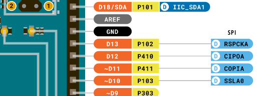
In the Arduino datasheet, we see that pin D13 is connected to P102 of the chip:

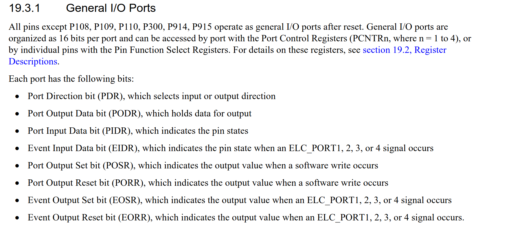
I then spent a while trying to figure out how to reference pin 102 in the ra4m1 crate. You actually need to set bits in a specific register to be able to use them. We see the following in the data sheet for the chip:

Se we need to set the PDR bit to select “output”, then the PODR bit to set this to high.
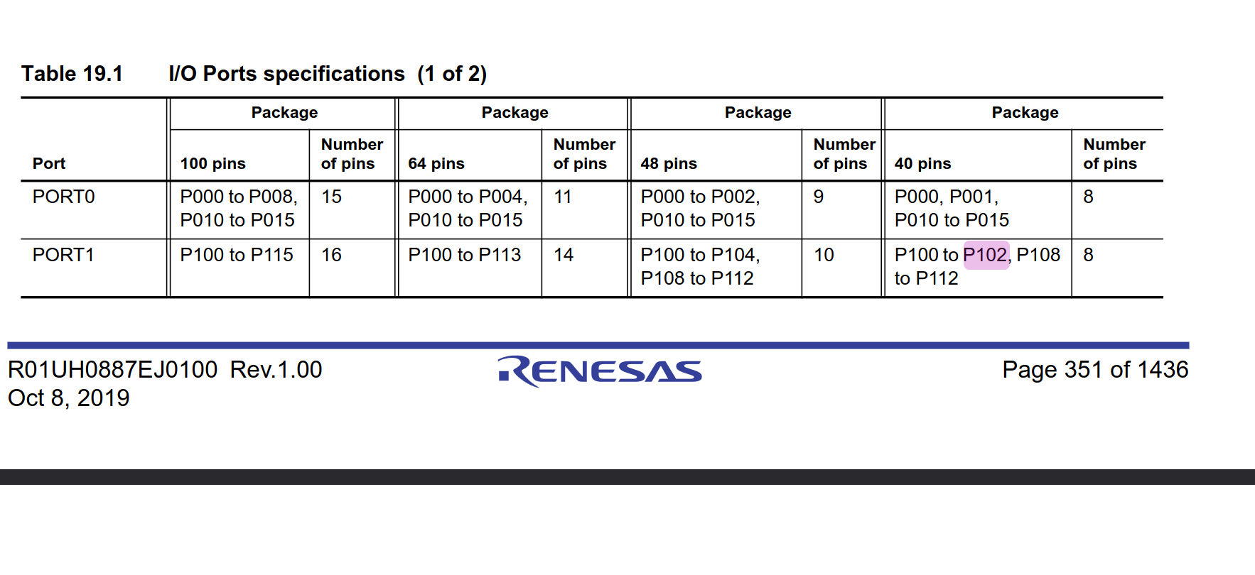
In the ra4m1 hal, these are referenced behind a “PORT”, specifically:

P102 is on “PORT1”, and I think this means I have to set the third bit (b2) of the port:

So we have something like this, which I think should at least do something:
#![no_main]
#![no_std]

use panic_halt as _;

use cortex_m_rt::entry;
use ra4m1;

#[entry]
fn main() -> ! {
    let p = unsafe { ra4m1::Peripherals::steal() };
    let port = p.PORT1;

    port.pdr().modify(|_, w| unsafe { w.bits(0b100) }); // set it to output?
    port.podr().modify(|_, w| unsafe { w.bits(0b000) }); // turn it off

    loop {
        port.podr().modify(|_, w| unsafe { w.bits(0b100) }); // turn it on?
        //sleep for a bit
        // port.podr().modify(|_, w| unsafe { w.bits(0b000) });
    }
}
This compiles! That means it will definitely work. I’m excited to see my arduino’s light turn on.
But…. It didn’t work! The LED just slowly pulses in an out, which is what happens when it is in “bootloader mode” (you can get here by double-tapping the reset button).
This is where I ended up in a spiral of despair, and was me mostly floundering.
I figured that if the arduino couldn’t find my code, then it couldn’t start! My guess was that the memory information used in the linker (memory.x) is what was causing the boot loop - the arduino didn’t know what to do.
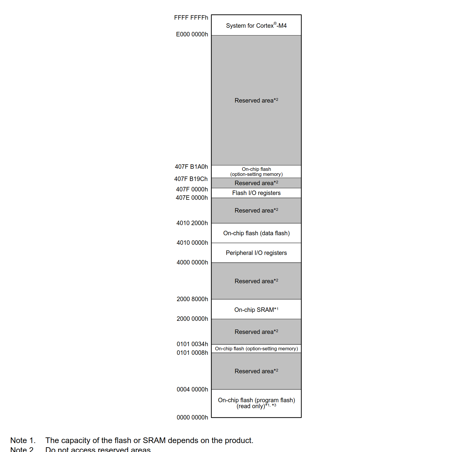
So… I spent a long time trying to glean the memory blocks from this image in the reference materials for the chip:

I wasn’t sure which ones were relevant to what I was doing.
I tried looking at the sizes in a bare arduino sketch:
❯  /home/farid/.arduino15/packages/arduino/tools/arm-none-eabi-gcc/7-2017q4/bin/arm-none-eabi-size -A /home/farid/.var/app/cc.arduino.IDE2/cache/arduino/sketches/9DC53CE91F29F6C0885D8121E1BB282E/BareMinimum.ino.elf
/home/farid/.var/app/cc.arduino.IDE2/cache/arduino/sketches/9DC53CE91F29F6C0885D8121E1BB282E/BareMinimum.ino.elf  :
section                    size         addr
.text                     57436        16384
.ARM.exidx                    8        73820
.fsp_dtc_vector_table         0    536870912
.data                       568    536870912
.noinit                      24    536871480
.bss                       6192    536871504
.heap                      8192    536877696
.stack_dummy               1024    536902400
.vector_table               256    536903424
.data_flash                   0   1074790400
.id_code                     28     16842776
.option_setting               0            0
.option_setting_ns            0            0
.option_setting_s             0            0
.ARM.attributes              48            0
.comment                    199            0
.debug_info             2464862            0
.debug_abbrev             93044            0
.debug_aranges             7192            0
.debug_ranges             24968            0
.debug_macro             161324            0
.debug_line              279977            0
.debug_str               582271            0
.debug_frame              24088            0
.debug_loc               159078            0
.stab                       180            0
.stabstr                    387            0
Total                   3871346
And then tried replicating that for the rust binary:
❯  /home/farid/.arduino15/packages/arduino/tools/arm-none-eabi-gcc/7-2017q4/bin/arm-none-eabi-size -A target/thumbv7em-none-eabihf/release/examples/hello
target/thumbv7em-none-eabihf/release/examples/hello  :
section            size        addr
.vector_table      1024       16384
.text               168       32768
.rodata               0       32936
.data                 0   536870912
.gnu.sgstubs          0       32960
.bss                  4   536870912
.uninit               0   536870916
.debug_loc          229           0
.debug_abbrev      1347           0
.debug_info        8585           0
.debug_aranges      472           0
.debug_ranges      1160           0
.debug_str         7310           0
.comment             64           0
.ARM.attributes      58           0
.debug_frame        692           0
.debug_line        2272           0
.debug_pubnames     702           0
.debug_pubtypes      71           0
Total             24158
But there are many different sections that don’t line up…
After a while, I realized I could just grab this from the “real” arduino codebase, and found fsp.ld which was the same format as memory.x. I think I need to read more about what this format is, and what it does (apparently it’s written in linker command language, which defines how the input files are linked to the output files).
Copying that file and removing references to C code didn’t work as the rust linker complained that things weren’t lining up, which is true, it maps the different parts of memory to the same addresses.
There is a whole section in that file called SECTIONS, which is provided by the cortex-m-rt crate and is automatically included
I think this is where the problem lies. The arduino file contains things like:
        /* .sketch_boot section supports the Arduino SxU libraries, which are second stage bootloaders.
         * The bootloaded sketch then starts aligned at next flash page after the SxU */
        KEEP(*(.sketch_boot))
Which I think means we need a sketch_boot section to bootstrap our code somehow?
This is a hole I haven’t yet dug myself out of, and might just say:
“This is impossible, for now!”