I've started writing my own sequencer firmware for the Yocto drum machine. In this post I will share what I have learned so far.
What
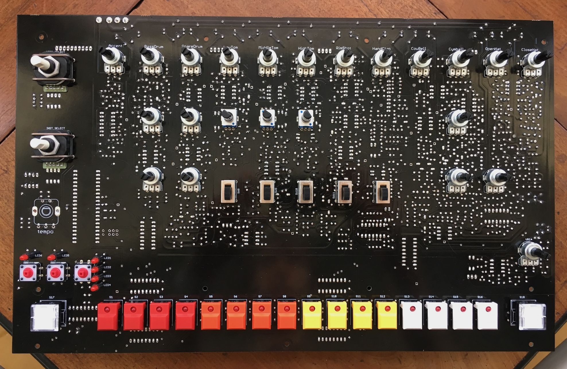
The Yocto is a DIY clone of the Roland TR-808 drum machine made by e-licktronic. It was my first music electronics DIY project. Because I like tinkering I made my own firmware for it, which was also my first experience with embedded development. So besides a musical instrument, it has also been a platform for experimentation for me.
Why
When I first wrote my own firmware for the Yocto I was mainly interested in remote-controlling the machine via MIDI. But recently I have become more interested in using the built-in sequencers of drum machines.
I have other drum machines with sequencers that can make 808 sounds but my ultimate goal is to make my own sequencer firmware for the Nava, the TR-909 clone sibling of the Yocto. The Nava is more complicated (it has a display, way more buttons, and it has velocity-sensitive sounds) so I thought it would be a good start by writing a Yocto sequencer first.
There isn't anything wrong in particular with the original firmware, I just like creating things myself.
How far did I get
As I write this I have a working tempo knob, 16 patterns of 16 steps that get saved to flash memory, step entry and tap entry. The most important thing that is missing to make it musically useful is (MIDI) sync.
What did I learn
I keep forgetting how to use GPIO
The Yocto has an ATmega1284P 8-bit AVR MCU, which is more or less an Arduino. I keep forgetting that in order to read from a general purpose input/ouput (GPIO) pin I need to use the PINA register, while for writing I need PORTA. I got stuck for hours not getting the tempo encoder working because I was trying to read from PORTA!
TWI / I2C is verbose
For some reason I have more experience working with SPI devices than with I2C. SPI and I2C are serial protocols, i.e. something like USB except for communcation between chips on a circuit board. AVR calls I2C "Two Wire Interface" (TWI).
The smart thing to do would probably be to use a library to handle the I2C protocol but because I like doing things myself I only used the register interface offered by the MCU. For my use case, I ended up with four verbs: twisend, twirecv, twistart and twistop. As an example, the procedure to prepare for reading from the flash chip then looks like this:
if (twistart() || twisend(FLASHADDR, 0) != TW_MT_SLA_ACK ||
    twisend(0, 0) != TW_MT_DATA_ACK || twisend(0, 0) != TW_MT_DATA_ACK)
    return;
if (twistart() || twisend(FLASHADDR | 1, 0) != TW_MR_SLA_ACK)
    return;
I am pleased with how this lets me write dense code without introducing a lot of new concepts but I wish it was all less complicated.
I came up with a new way to specify IO port configuration
The general-purpose IO ports of the MCU have fixed functions in the hardware; the software must somehow "know" this. Before I used a table (an array of structs) in the main program. Now I made a code generator that lets me name the GPIO pins and that generates accessor and initializations functions for the named pins.
For example the list of output pins looks like this:
struct {
    char *name, port, bit;
} outports[] =
    {
    {"TRIG_OUT1", 'B', 0}, {"TRIG_OUT2", 'B', 1},
    {"TRIG_CPU", 'B', 2},  {"LATCH_SW", 'B', 3},
    {"LATCH_LED", 'B', 4}, {"SPI_OUT", 'B', 6},
    {"SPI_CLK", 'B', 7},   {"COM_SW1", 'A', 0},
    {"COM_SW2", 'A', 1},   {"scale4", 'C', 2},
    {"scale3", 'C', 3},    {"scale2", 'C', 4},
    {"scale1", 'C', 5},    {"Aled", 'C', 6},
    {"Bled", 'C', 7},      {"TRIG_OUT3", 'D', 6},
    };
This means that pin PORTB0 is called "TRIG_OUT1". The generator then creates setter functions like this:
void setTRIG_OUT1(uint8_t x) {
    if (x) PORTB |= 1<<0;
    else PORTB &= ~(1<<0);
}
The code generator has a subtle advantage: the generated code is specialized to each pin. This lets the compiler emit faster instructions for toggling bits (cbi and sbi).
I still don't really understand rotary encoder debouncing
I always struggle with writing rotary encoder debouncing code, i.e. code that doesn't miss clicks. The type of encoder in the Yocto (Bourns PEC16) has a state diagram like this:
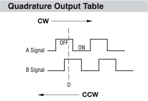
For each direction there are four state changes. Because there are two encoder pins we have to check each time (A and B), it is convenient to store them interleaved in the debouncer. Looking at the bit patterns for the state changes I noticed that there are pairs of inverses, so there are really only two state changes per direction, that each get mirrored.
A high, B rising
A 1 1 1 1, B 0 1 1 1
Interleaved: 0 1 1 1 1 1 1 1
Interleaved hex: 0x7f

A falling, B high
A 1 0 0 0, B 1 1 1 1
Interleaved: 1 1 1 0 1 0 1 0
Interleaved hex: 0xea

A low, B falling
A 0 0 0 0, B 1 0 0 0
Interleaved: 1 0 0 0 0 0 0 0
Interleaved hex: 0x80

A rising, B low
A 0 1 1 1, B 0 0 0 0
Interleaved: 0 0 0 1 0 1 0 1
Interleaved hex: 0x15
Knowing this I was able to write a short debouncing function:
int updateencoder(uint8_t *history, uint8_t bits) {
    *history = (*history << 2) | (bits & 3);
#define M(x, y) ((x) == (y) || ~(x) == (y))
    return M(*history, 0x7f) + M(*history, 0xea) - M(*history, 0xbf) -
           M(*history, 0xd5);
#undef M
}
It seemed to work for a while but now it got worse again: it misses clicks when I turn the dial too fast. Maybe I'm not sampling often enough?
Actual sequencer functions are simple to write
While things do get cluttered, most actual sequencer functions are quite compact. For example, the archetypical 808 interface behavior of toggling drum hits with the step keys is
just a XOR in the current pattern pat.
for (i = 0; i < STEPS; i++)
    if (bitset(pressed, i))
        pat[i] ^= instrumentmask;
What's next
I would like to add MIDI sync, and maybe things like pattern chaining (like on the 606), variable pattern length and prescalers (for triplets and 32nd notes). But MIDI sync is the big thing, it would allow me to make music with this firmware.
Conclusion
None of what I built here has been "necessary" for something but I like learning and sometimes it's nice to have a just-for-fun programming project like this.